What Parameters Should be Noted for Patch Fuses

A circuit is composed of wires and electronic components, and the parameters of SMD fuses(patch fuses) required by different circuits vary. The main parameters of SMD inductors include inductance, allowable deviation, distributed capacitance, rated current, and quality factor.
1. The magnitude of inductance mainly depends on the number of turns (turns) of the inductance coil, the winding method, the presence or absence of a magnetic core, and the material of the magnetic core. Usually, the more coils there are, the denser the wound coils, and the greater the inductance. A coil with a magnetic core has a greater inductance than a coil without a magnetic core. The higher the permeability of the magnetic core, the greater the inductance. So there are many factors that determine the magnitude of inductance. The basic unit of inductance is Henry, denoted by the letter "H". Commonly used units include milliohms (mH) and microohms(μH) The relationship between them is: 1H=1000mH; 1mH=1000μH
2. The allowable deviation between the labeled sensitivity and the actual sensitivity. The chip inductance commonly used in oscillation or filtering circuits requires high accuracy, with an allowable deviation of ± 0.2%~± 0.5%; The accuracy requirement for coupling or high-frequency resistance current is not high, with an allowable deviation of ± 10%~15%.
3. The capacitance between turns and between coils and magnetic cores of distributed capacitance coils. The smaller the distributed capacitance, the better its stability.
4. The maximum current allowed to pass through when the rated current chip inductor is working normally. If the working current eXCeeds the rated current, it will burn out.
5. Quality factor, also known as Q-value or goodness of merit, is the main parameter used to measure the quality of inductors. He refers to the ratio of the inductance presented by the chip inductor to its equivalent loss resistance when operating at a certain frequency of AC voltage. The higher the Q value, the smaller the loss and the higher the efficiency.
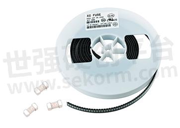
Fig.1
- +1 Like
- Add to Favorites
Recommend
This document is provided by Sekorm Platform for VIP exclusive service. The copyright is owned by Sekorm. Without authorization, any medias, websites or individual are not allowed to reprint. When authorizing the reprint, the link of www.sekorm.com must be indicated.
Integrated Circuits


Discrete Components


Connectors & Structural Components


Assembly UnitModules & Accessories


Power Supplies & Power Modules


Electronic Materials


Instrumentation & Test Kit


Electrical Tools & Materials


Mechatronics


Processing & Customization


