Tips for How to Design The Duplex Hands-free Calling Products of The Microphone

Due to the global pandemic issue in 2020, many people have had to adapt to an entirely new work style: Working from home. WFM has increased the demand for Speakerphone and video conferencing products that require superior sound quality even in a noisy environment.
It’s important to accelerate the development time, but the engineer needs to spend a lot of time in the mechanical design and sound adjustment of the microphone and speaker; it also requires spending time going to the acoustic lab for fine-tuning frequently. You will miss out on the time to the market if you are not familiar with the design criteria of acoustic components.
Especially the microphone, a highly sensitive acoustic component, not only receives tiny sound signals in the air but also receives the conductive resonance and harmonic distortion from the speaker vibration and mechanism on the product. These non-linear signals will make the DSP can’t effectively process the AEC signal and you will hear the echo sound easily. It will decline the quality of the call or the voice you’d like to catch.
Therefore, here are some tips for how to design the Duplex Hands-free Calling Products of the microphone.
1. Mic Array
Mic Array is formed by 2 to 8 pcs microphones and combined with DSP & Beamforming algorithm; it could achieve Voice Far Pickup & Noise reduction to improve the quality of voice call.
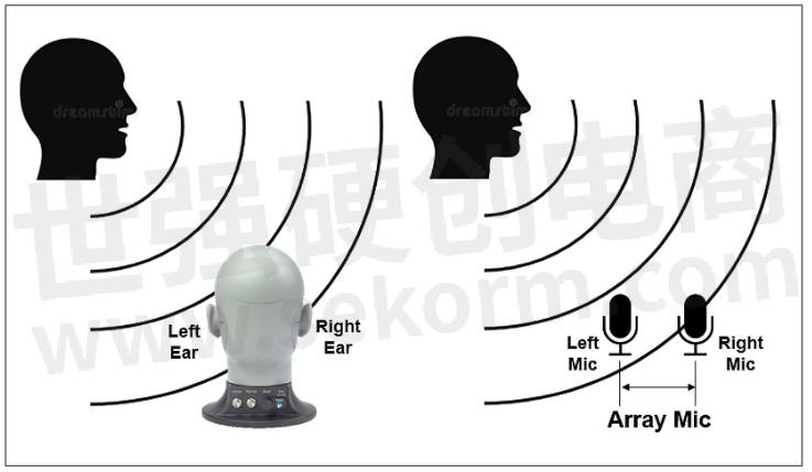
Human ears can distinguish the direction of the sound, we could use 2 microphones to achieve directional sound receive.
2. Mic Sensitivity & Fr
The sensitivity of each microphone of Mic Array should be close to the Fr, ideally is ±1dB, which can reduce the deviation of DSP during calculation, and the total length of the sound tunnel structure should not exceed 5mm and avoid the resonance frequency of the microphone channel <12KHz.
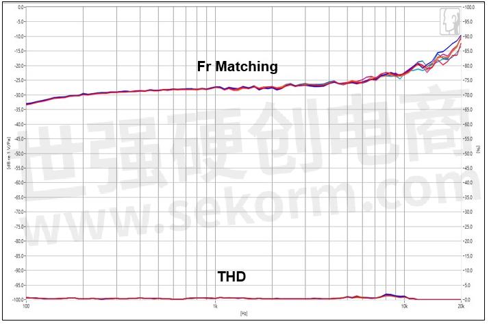
Figure 2. Microphone frequency response matching
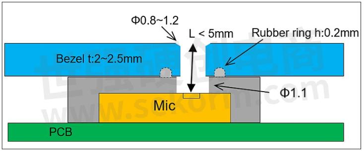
Figure 3. Microphone rubber holder and bezel
3. Mic Phase
Every Mic phase should be closer to each other will be better, ideally is ±5∘, it could reduce the time of deviation when DSP is working on calculation and ensure the accuracy of Beam & Directivity.
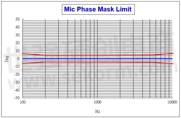
Figure 4. Microphone phase matching test
4. Mic Rubber Holder Sealing: The microphone rubber holder and Bezel must be truly sealed, and the sound insulation must be at least 20dBSPL to prevent the sound of the internal speaker of the product from entering the microphone's sound tunnel through the rubber gap.
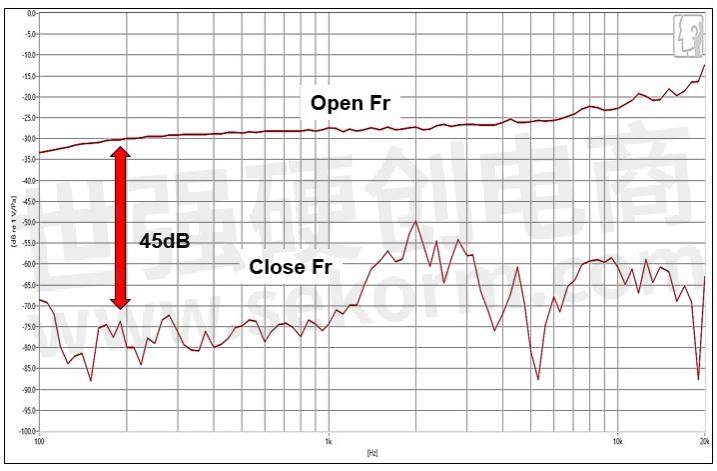
Figure 5a. Microphone rubber holder and bezel sealing
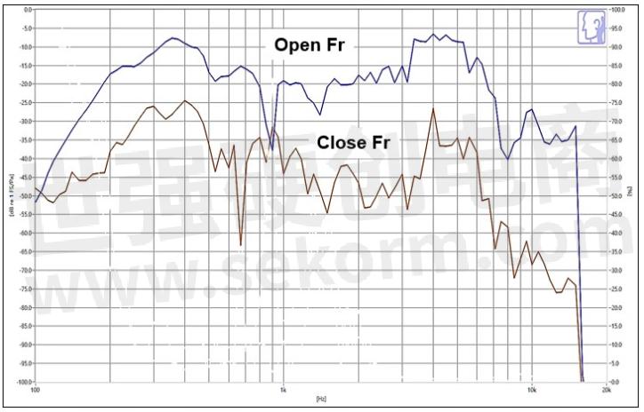
Figure 5b. Microphone record the sound of the speaker (microphone airtight frequency response test)
5. Mic vs Speaker location and shock-proof: Considering the speaker amplification and microphone's AEC signal processing, usually we will put the speaker placed in the middle, and the microphone should be placed far away from the speaker, the microphone also needs to use the rubber to shock-proof and airtight. The box speaker and the shell where contact the surface, screw's hole needs use sponge or rubber holder to avoid the vibration or the microphone will receive the THD signal from the speaker, it will affect the quality of the AEC.
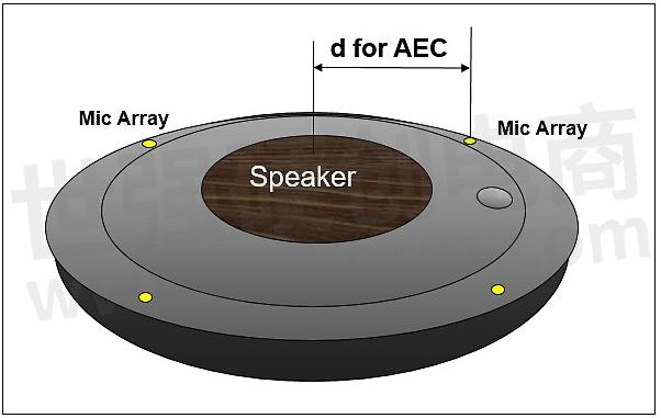
Figure 6a. The position and the distance of the microphone and the speaker
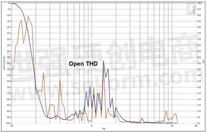
Figure 6b. Microphone record the sound of the speaker (microphone THD test)
If customers could follow the notice above and also follow the Audio Codec Design Guide it could greatly shorten the debugging time and enable the product to be launched on time
- +1 Like
- Add to Favorites
Recommend
- Differences between Full-duplex and Half-duplex Sensor Monitoring System
- What Are Simplex and Duplex Fiber Patch Cords?
- SA618F30-FD Full-Duplex Module with 8-Channel Concurrency,Addressing the Latency, Channel Congestion, and Concurrent Communication Limitations of Traditional Half-duplex Systems
- Things You Need to Know About Combiner and Duplexer
- 24-lane 120G Full-duplex Embedded Optical Transceivers for Harsh Environment Applications, Offering Market Leading I/O Density and Satisfy
- Application of the SA628F30 Full-Duplex Module in Helmet Systems
- What is a Single and Duplex Wireless Module?
- Kingstate Signs an Authorized Distributor Agreement with Sekorm
This document is provided by Sekorm Platform for VIP exclusive service. The copyright is owned by Sekorm. Without authorization, any medias, websites or individual are not allowed to reprint. When authorizing the reprint, the link of www.sekorm.com must be indicated.
Integrated Circuits


Discrete Components


Connectors & Structural Components


Assembly UnitModules & Accessories


Power Supplies & Power Modules


Electronic Materials


Instrumentation & Test Kit


Electrical Tools & Materials


Mechatronics


Processing & Customization


