SanDeYing Electronic PCB 3D Models Provides A Clear View of All The Parts on PCB Boards in 3 Dimensions Length, Width, and Height

The 3D model provides a clear view of all the parts on PCB boards in 3 dimensions length, width, and height. So that it helps to select suitable-sized parts, optimize the layout and fit the PCB inside an enclosure.
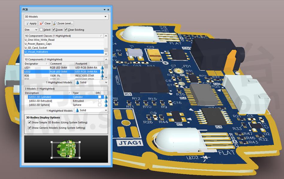
The PCB panel allows you to browse the current PCB design using a range of filter modes to determine which object types or design elements are listed, highlighted, or selected. The panel also has editing modes for specific object types or design elements that provide dedicated controls for editing procedures. Note that you can access the properties for any element listed in the panel.
The three main list regions of the panel when in 3D Model mode reflect, in order from the top:
1. Component classes.
2. Specific components associated with the component class that has associated 3D body object(s) or free models (non-PCB mounted, free-floating 3D bodies).
3. The individual 3D bodies for each component or free model.
Panel Access
When the PCB Editor is active, click the PCB button at the bottom-right corner of the workspace and select PCB from the context menu. Alternatively, you can access the panel through the View » Workspace Panels » PCB » PCB sub-menu.
Panels can be configured to be floating in the editor space or docked to the sides of the screen. If the PCB panel is currently in a group of panels, use the PCB tab located at the bottom of the panels to bring it to the front.
Browsing 3D models
The PCB panel's filter scope progresses through component classes to components and their constituent model elements, while the visual result tracks the changes.
As you click on a specific component in the Components region of the panel, filtering will be applied using the component as the scope of the filter. The visual result (in the design editor window) is determined by the highlighting methods enabled (Mask/Dim/Normal, Select, Zoom). Multiple rule entries can be selected using standard Shift+Click and Ctrl+Click features.
Double-clicking a component entry in the Component region of the panel (or right-clicking and choosing Properties) will open the relevant Component dialog, from which you can edit its properties in detail.
Similarly, double-clicking a model entry in the Models region of the panel (or right-clicking and choosing Properties) will open the relevant 3D Body dialog, from where you can edit the complete 3D body properties.
When selecting a component's constituent models from the Models list area in the PCB panel, the view in the editor workspace will zoom, dim/mask, or select accordingly.
An individual model is selected from a component. In this case, a cylinder from a LED component in the board's U_Visual_Indicators class.
The PCB panel can be used to select display properties for 3D models. The cone icons represent different levels of transparency from 100% (hidden) down to 0% (solid) in increments of 25%. You can select multiple components and apply the same display controls to them at once using the Highlighted Models options.
The selected cylinder model is set to 75% opacity. Multiple models can also be selected and changed in one step.
Enable the DRC checkboxes for models you want to be flagged for analysis under the Placement » Component Clearance rule.
The 3D Bodies Display Options controls allow you to control the display of 3D bodies without having to modify the current view configuration. Display options set from the PCB panel are not saved as part of the view configuration.
Multiple Model entries can be selected using standard Shift+Click and Ctrl+Click features, providing full control over the 3D Model view and the base 3D elements that make up a component.
Here, both a cylinder (set to 75% opacity) and a sphere (solid / 0% opacity) from a LED component are selected.
3D Body Display Options
Show Simple 3D Bodies (Using System Setting) - Enable this option to display simple 3D bodies on the PCB. This option is enabled by default.
Show Generic Models (Using System Setting) - Enable this option to display generic models on the PCB. This option is enabled by default.
- +1 Like
- Add to Favorites
Recommend
This document is provided by Sekorm Platform for VIP exclusive service. The copyright is owned by Sekorm. Without authorization, any medias, websites or individual are not allowed to reprint. When authorizing the reprint, the link of www.sekorm.com must be indicated.
Integrated Circuits


Discrete Components


Connectors & Structural Components


Assembly UnitModules & Accessories


Power Supplies & Power Modules


Electronic Materials


Instrumentation & Test Kit


Electrical Tools & Materials


Mechatronics


Processing & Customization


