Renesas RH850/C1M-Ax MCU Solves Complex Control Challenge in Integrated Dual Traction Inverter
The automotive electrification trend to accelerate ongoing global shift toward carbon neutrality has exponentially increased in recent times. Penetration of xEV vehicles is advancing alongside with stricter environmental regulations, core technology innovations and falling costs.
Nearly every region of the world is striving for tighter environmental regulations, where Europe is a leader, while Green House Gas (GHG) standards in other regions are following closely. One additional influential factor is that stricter GHG emission standards can be expected especially for the United States, now lead by a new government. This may lead to revitalized growth especially for HEV because this vehicle category could act as an early available solution in the transition phase towards BEV. Although mild hybrid (48V systems) is contributing to meet the new GHG standards, it will not be enough from the OEM point of view to avoid fines from not meeting the CO2 emissions regulations of each respective country.
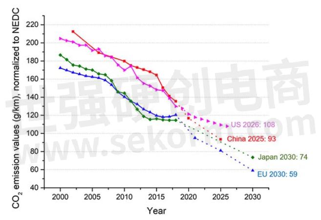
Figure 1: GHG Regulation Per Country / Region (Source: ICCT, 2020)
As this GHG trend is accelerating, expectations are that the worldwide xEV market might be heading into a time of lengthy expansion, with lowering battery costs. Tighter restrictions (fuel economy standards/BEV sales regulations) in countries across the board will create demand through around 2025, followed by a transition to a pattern of independent growth from 2025 onward as the core technology gradually becomes cheaper, including batteries.

Figure 2: Global xEV Demand Forecast of Light-duty Vehicles (Excludes 2/3-wheelers, Medium/Heavy Duty Buses & Trucks etc.) Source: Strategy Analytics - Automotive Electronics System Demand - April 2021
HEV System Requirements and Concept
PHEV and FHEV especially, depending on the respective system concepts, have a higher complexity from a cooperative control strategy point of view (ICE and Electric drive). On top of that are more sensitive to space restrictions of the application components simply due to the combination/addition of the ICE and e-drive functions. This is not only true for the electro-mechanical components, but for the electronics as well, such as digital chipset, analog and power components.
The described system complexity results from the following top-level functionality:
· At vehicle deceleration, kinetic energy is converted into electric energy by the e-motor and stored in the battery.
· During acceleration, electric energy from the battery is used to assist the ICE, thus fuel consumption is saved.
· A high-powered e-motor for an FHEV means having high generator capacity so that more kinetic energy can be recovered (or recuperated) during deceleration, resulting in fuel efficiency improvement in the range of several 10s of percent.
HEV Control: A Complexity Concept

Figure 3: HEV Top-level Concepts
There are several kinds of hybrid architectures, where Figure 3 describes a top-level overview. The simplest one is a Parallel hybrid system. A motor is placed in parallel with an ICE. The motor/generator assists acceleration by using electric energy from the battery and recharges the battery by using the motor as generator during deceleration. The benefit of this system is lower cost and less control complexity.
In the case of the Series Hybrid system, the kinetic energy created by the ICE is converted to electrical energy by a generator, and the electrical energy is used to generate kinetic energy again by another motor. This may seem like it is wasting cost and energy. However, the advantage of this approach is that it allows operating the ICE in the most fuel-efficient speed/torque range. An ICE has poor fuel efficiency at low speeds (e.g., < 1500rpm), high speeds (e.g., > 4000rpm), and low torque regions.
The Series/Parallel hybrid is the most complicated system. When the ICE is operating in a fuel-efficient speed/torque range, the ICE output can be directly transferred to the wheels through a clutch and transmission. If torque assistance is needed, the e-motor can assist with acceleration and the ICE can save fuel like in a Parallel hybrid system. When vehicle speed is very slow, the clutch is disengaged, and the system behaves as a Series hybrid to avoid operating the ICE in a poor fuel-efficiency range.
In the case of Series and Series/Parallel hybrid system configurations, usually a combination of two motor/generator devices need to be tightly and inter-dependently controlled.
HEV Control: Key Challenge and Solution
From the previously introduced traction motor system concepts, it becomes obvious that the respective control and synchronization efforts especially in the case of the Series/Parallel hybrid system are complex, because of a high communication load between both entities as well as increased diagnostics efforts to maintain the targeted ASIL-level.
An obvious solution to optimize these efforts is to integrate both Inverter control systems into one ECU, operated by a single and highly specialized Microcontroller (MCU). By using such a concept, the synchronization between both inverter control loops can be implemented with one controller, resulting in high communication bandwidth and short latency. Furthermore, the diagnostics & Functional Safety concepts will become more straight forward with the selection of an ASIL compliant target device. Another benefit of an integrated solution is certainly a strongly optimized Bill-of-Material (BOM) which goes along with reduced component space requirements, both highly welcome effects for the overall system concept.
Solution: MCU with Integrated xEV Support Features
A key asset for HEV application specific MCUs is to offload the calculation process of vector math for the motor control algorithm to a dedicated processing IP. By using this method, the MCU can be equipped with a smaller number of CPU cores while taking over other software tasks as described above.
Enhanced Motor Control Unit (EMU3)
The embedded “Enhanced Motor control Unit 3” (EMU Gen3) is a set of individual motor control accelerator modules that calculate the 3-phase PWM compare values using a vector control algorithm, generating rectangle wave patterns based on the motor current values measured by an A/D converter. Additionally, the motor's angle value is obtained through an integrated “Resolver to Digital Converter” (RDC3A), performing the Position sensor interface function. The calculation results of the EMU3 are used by the TSG3, a 3-phase motor timer, to output PWM and rectangle waves.

Figure 4: Enhanced Motor Control Unit
The EMU3 IP can exercise motor-control functions in combination with user specific software interventions between any of its functional blocks. Thus, a flexible control concept combining hardware acceleration and individual user software can be realized.

Figure 5: Flexible Motor-control in Combination with User Specific Software Interventions
Dual e-Motor/Generator Control
The key solution to achieve dual e-motor/generator control capability is based on how the previously introduced motor-control IP (“EMU3”), as well as the embedded position sensor interface are incorporated into the MCU system.
The following diagram shows the actual approach to control two e-motors (please refer to the Appendix for abbreviation definitions):
· CPU2 and CPU3 are each controlling one motor, respectively. By using the EMU3, the processing of performance-intensive motor-control algorithms, like the Park/Clark-transformation for PWM pattern generation, is shifted from the CPU to the EMU3. This allows the movement of other important software tasks, like diagnostic processing, to be performed by the CPUs.
· CPU1 can be used for other functions: i.e., to realize DC/DC converter control as an optionally integrated add-on feature to optimize the overall HEV system layout.
· RDC3A is the MCU integrated (Tamagawa AU6805-equivalent) dual Resolver-to-Digital Converter interface, or more generically, the motor position sensor interface, capable of connection to analog resolver- or inductive position sensor signals.

Figure 6: System Example to Control Dual e-Motor/Generator
Solution Offering by Renesas
At Renesas, generations of well-proven concepts for HEV-control exist within the 40nm MCU-RH850/C1M-Ax. This device, and its soon to be released 28nm successors, focus on Inverter control functions for traction motors. Suitable PMICs, gate drivers and IGBT devices, as well as inverter turnkey solutions can significantly reduce customers’ R&D efforts (see Fig. 7).

Figure 7: Renesas xEV Portfolio
Summary
Hybrid vehicles which are operating based on a combined e-drive / ICE system are especially in need of cost-efficient and size-optimized propulsion systems due to the increased system complexity. Traction-inverter specific high-performance microcontrollers (MCUs) included with a dedicated HW accelerator function for vector math calculations can help to achieve an overall optimized electronic and electro-mechanic system design.
- +1 Like
- Add to Favorites
Recommend
- Renesas RH850 Series Contributes to the Realization of a Flying Motorcycle
- Renesas and FAW Establish Joint Laboratory to Accelerate Development of Next-Generation Smart Vehicles
- Renesas MCUs Can Rewrite The Update Software by Wireless Communication with OTA Technology
- Renesas 48V Proof-of Concept (PoC) Solution for Checking and Identifying xEV System Level Requirements
- Renesas Expands Lineup of 28nm Cross-Domain Automotive Control Microcontrollers
- Renesas R-Car SoC and RH850 MCU to be Used in Honda SENSING System
- Pairing An R-Car SoC Microprocessor with RH850 and PMIC, System Solution for CoGW ECUs Can Be Realized
- Silicon Labs Expands MCU Platform with a 50MHz Core Frequency New BB5 8-bit MCU Family
This document is provided by Sekorm Platform for VIP exclusive service. The copyright is owned by Sekorm. Without authorization, any medias, websites or individual are not allowed to reprint. When authorizing the reprint, the link of www.sekorm.com must be indicated.
Integrated Circuits


Discrete Components


Connectors & Structural Components


Assembly UnitModules & Accessories


Power Supplies & Power Modules


Electronic Materials


Instrumentation & Test Kit


Electrical Tools & Materials


Mechatronics


Processing & Customization


