Integrated GaN Power Stage for eMobility with BLDC motor

GaN FETs and ICs offer the ability to operate at much higher frequencies in hard-switching topologies without incurring significant losses. In March, EPC introduced a new monolithic GaN halfbridge ePower™ Stage IC that is capable of 1 MHz switching and up to 15 ARMS load current per phase. This tiny IC greatly reduces PCB size. The system size, however, is further diminished because the very high frequency reduces filtering requirements, thus reducing size and weight. One application example that will be discussed is an eScooter (Figure 1) with a 400 W BLDC motor.
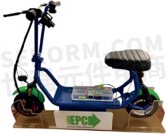
Figure 1: eScooter powered by a 400 W BLDC motor driven by EPC2152 ePower Stage ICs
High-frequency switching drives for BLDC motors
Due to the structure of the brushless DC (BLDC) motor, most will be powered by a three-phase inverter also known as a motor drive. Different applications place different requirements on the motor and drive system; for example, drones require efficiency, speed, and must be lightweight; while e-bikes require high efficiency and high torque capability.
Many motor drives operate at 20 kHz but can go as high as 60 kHz, and selection for a given application is driven by cost constraints, power losses, audible limitations, EMI regulations and maximizing mechanical life for the motor. Some other application requirements, such as precision, may be difficult to achieve when limited to using 20 kHz, necessitating a higher switching frequency.
Additional benefits of operating at a higher switching frequency include:
· Lower AC component magnetic losses due to lower ripple current magnitude and thus higher motor efficiency and lower operating temperature,
· lower filtering requirements thus reducing filter size, volume, and weight of the inverter,
· lower THD at higher motor frequencies that keeps audible emissions low,
· supports newer class of low inductance motors such as slot-less motors.
Inverter switching with GaN FETs and ICs
Higher inverter switching frequency does have the disadvantage of higher inverter operating losses, particularly when using MOSFETs. This is in large part due to reverse recovery charge (QRR) and other dynamic characteristics of MOSFETs. GaN FETs, with zero reverse recovery and low hard-switching losses, can overcome these high frequency inverter limitations and have already been demonstrated in several motor drives. EPC is now taking it to the next level by using a monolithically integrated GaN half-bridge power stage that can reduce the inverter size, weight and increase operating frequency further.
The next evolution for GaN FETs is monolithic integration of the power FETs and complete half-bridge gate driver. There are many benefits to monolithic integration of the power stage such as:
· It virtually eliminates common source inductance (CSI), and reduces the power loop and gate loop inductances.
· The gate drivers are matched to the FETs and can be designed to optimize switching speed against EMI, voltage spikes, and efficiency resulting in the shortest practical transition times.
· It improves thermal power dissipation distribution allowing optimized FET scaling that yield higher efficiencies. This feature is more useful for high stepdown ratio converters.
· It improves dv/dt immunity that covers all eight types of switch-node transition events.
· It simplifies PCB layout and reduces assembly component count for the converter solution.
eGaN ePower™ stage
Figure 2(a) shows the block diagram of the EPC2152 GaN ePower™ Stage. The main FETs are controlled by gate drivers within the IC that includes input buffers, a logic interface with Power-On-Reset (POR), Under-Voltage-Lockout (UVLO) functions, a high voltage, high dv/dt capable control signal level-shifter and a synchronous bootstrap that ensures proper high side voltage for the high side gate driver.
The EPC2152 device is capable of interfacing to digital controllers that use standard CMOS or TTL logic levels, allowing it to be driven directly from a digital controller with 3.3 V signal levels, or from analog controllers that use voltage levels up to 12 V.
Figure 2(b) shows a die photograph of the monolithic GaN power stage with pin allocations. It measures only 3.9 mm by 2.6 mm, or 10 mm2 . Both FETs are rated at 80 V, and each has a typical RDSon of 10 mΩ. This IC can conduct peak motor phase load currents up to 15 A. Figure 3 shows a block diagram of a BLDC motor drive inverter featuring all the essential elements required for a high-performance drive ideal for electric mobility.

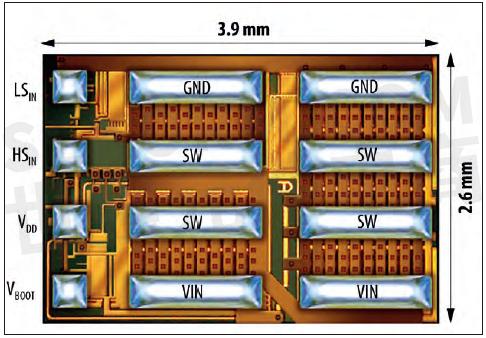
Figure 2 (a) : Block diagram of the monolithic GaN ePower Stage Figure 2(b) below: die of the EPC2152

Figure 3: Block diagram of the BLDC motor drive inverter
Each of the half-bridge power stages use one EPC2152 ePower Stage and require only a few support capacitors, as can be seen in Figure 4 (top side) and is shown in a zoomed-in image in Figure 5. The motor phase currents are measured using shunts where the voltage is amplified using a high-performance shunt amplifier. Voltage measurement is from each phase to ground using a simple voltage divider resistor network. The same technique is used for the supply voltage measurement.
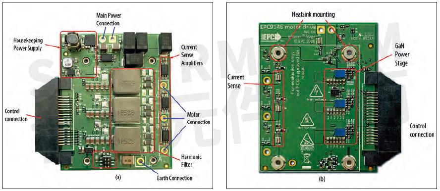
Figure 4: PCB (top and bottom side) of the 3-phase experimental BLDC motor drive (expl: a top, b bottom side)
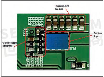
Figure 5: Zoomed-in photograph of the EPC2152 ePower Stage with support components as designed in the inverter PCB
Due to the high dv/dt’s generated by the GaN FETs, an LC-filter is included that can be configured as either a harmonic filter or EMI filter and comprises a line inductor and shunt capacitor. When configured as an EMI filter, a resistor is placed in series with the capacitor. This LCfilter is shown in Figure 4 (top side).
BLDC motor drive for eScooter
The motor drive is designed to operate from 15 V through 60 V DC input and power a 400 W BLDC motor such as the one used in the eScooter shown in Figure 1. It can operate from 20 kHz through 1 MHz switching frequency and deliver a peak current of 15 A into each phase of the motor when a heatsink is attached. The board measures just 45 mm × 55 mm.
To demonstrate the achievable performance of this BLDC drive, the inverter was operated from a 48 V DC supply voltage while switching at 100 kHz to power a 400 W motor with a sinusoidal modulation frequency of 20 Hz (rotational speed of the motor). The dead times for the half bridges were set to 10 ns for both the rising and falling edges and are very short when compared to MOSFETs that start at 50 ns.
Figure 6 shows the measured waveforms on a motor modulation frequency time scale. The drive is operated in an open loop and thus there is no controller to compensate for operationinduced distortions. The measured power loss as a function of one-phase RMS motor current for this drive is expected to exceed 98.4 % in real world conditions.
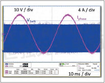
Figure 6: Motor modulation frequency (20 Hz) timescale measured switch-node and phase-current waveforms of the drive when operating from a 48 V DC supply and delivering 10 ARMS per phase into the motor
Conclusion
GaN FETs have demonstrated high switching frequency capability in BLDC motor drives, and the advent of a monolithically integrated half-bridge FET with full-function gate driver was demonstrated by powering a 400 W capable BLDC motor. The monolithic integration of the FETs and the gate driver ensures low switching losses and enables high switching frequency for the drive. Higher switching frequencies for the drive, together with simple EMI filtering reduces motor loss, keeps audible emissions low even at high speed, and saved significant weight and space. The result is a compact drive solution that could easily be integrated inside the motor housing for further cost, size, and weight savings.
GaN-on-Si devices, such as the ePower Stage EPC2152, are a major step toward developing full power systems-on-a-chip. Over the next few years there will be many more such products introduced to the market, each one reducing design time while improving system efficiency and cost. The era of the discrete transistor is coming to a close.
- +1 Like
- Add to Favorites
Recommend
This document is provided by Sekorm Platform for VIP exclusive service. The copyright is owned by Sekorm. Without authorization, any medias, websites or individual are not allowed to reprint. When authorizing the reprint, the link of www.sekorm.com must be indicated.
Integrated Circuits


Discrete Components


Connectors & Structural Components


Assembly UnitModules & Accessories


Power Supplies & Power Modules


Electronic Materials


Instrumentation & Test Kit


Electrical Tools & Materials


Mechatronics


Processing & Customization


