Signal Analysis in 5G NR Base Station Transmitters: Part 3

In this blog, we will focus on unwanted emissions testing as another requirement defined by 3GPP standards when performing the signal analysis (spectrum analysis) on base station transmitters.
Unwanted emissions are out-of-band and spurious emissions and can be analyzed using a signal analyzer (spectrum analyzer). The out-of-band emissions are the unwanted emissions immediately outside the channel bandwidth resulting from the modulation process and non-linearity in the transmitter but excluding spurious emissions. Spurious emissions are emissions caused by unwanted transmitter effects such as harmonics emission, parasitic emission, intermodulation products, and frequency conversion products, but exclude out-of-band emissions.
The base station transmitter's specified out-of-band emission requirements are adjacent channel leakage ratio (ACLR) and operating band unwanted emissions (OBUE). These requirements target the emission impact to different frequency offsets. ACLR only focuses on the power leakage to its adjacent channels, while the OBUE covers the entire operating band as well as an offset at each side. By using a signal analyzer (spectrum analyzer) you can analyze all these unwanted emissions when evaluating your base station transmitter signal quality.
ACLR Measurements
ACLR is the ratio of the filtered mean power centered on the assigned channel frequency to the filtered mean power centered on an adjacent channel frequency. The purpose of ACLR is to control the power leakage to adjacent channels under a certain level to reduce interference. The transmitted signal could be single or multicarrier, and the requirements apply to both.
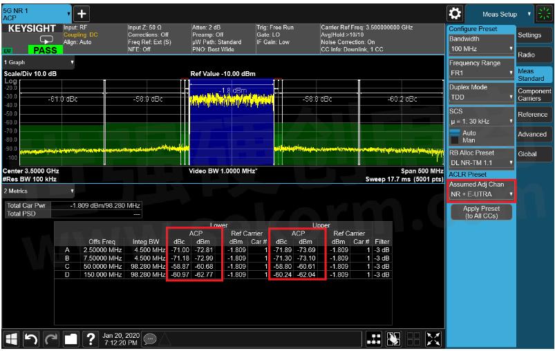
Figure 1 is an example of the signal analysis (spectrum analysis) of a conducted ACLR result using Keysight's UXA signal analyzers (spectrum analyzers) and PathWave X-Series measurement applications. The base station is transmitting 100MHz test model 1.1 for frequency range (FR)1, and it's a single carrier signal at a frequency of 3.5GHz. The metrics table displays the information for ACLR measurement, including total carrier power, frequency offsets, integration bandwidth for each offset, the measured ACLR, and the absolute power value. This signal analysis (spectrum analysis) also provides the flexibility to customize the pass / fail criteria, representing only the ACLR, only absolute power, and ACLR and/or absolute power. Similar to other measurements, a preset is also available for ACLR. Therefore, the signal analyzer (spectrum analyzer) can automatically configure the adjacent channel offset, bandwidth, and limit, based on the frequency band, base station type, class, and category.

Figure 1. An example of conducted lower ACLR measurement using Keysight's UXA X-Series signal analyzer (spectrum analyzer)
OBUE Measurements
OBUE measures the emissions close to the assigned channel bandwidth of the wanted signal while the transmitter is in operation. The defined unwanted emissions from the operating band measure the out-of-channel emissions over the whole base station transmitter operating band with an offset on each side. These are the unwanted emissions resulting from the modulation process and non-linearity in the transmitter but excluding spurious emissions.
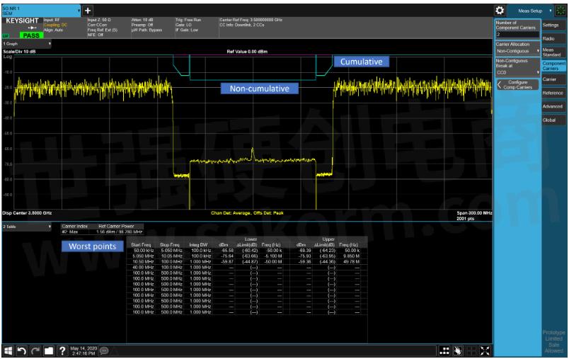
Figure 2 is a signal analysis (spectrum analysis) example of two-component carrier signals with the non-contiguous spectrum in a conducted test setup, using Keysight's UXA signal analyzers (spectrum analyzers) and PathWave X-Series measurement applications. This example refers to the measurement within a sub-block gap at 100MHz; the measured trace is displayed in multiple segments, together with the blue line on the top that shows the limit mask within the sub-block gap. This result includes the cumulative region with a stop frequency of 10.5MHz and also the non-cumulative region with a fixed limit value, consistent with the 3GPP required mask. The table in the figure reports the worse point in each segment at both upper and lower sides, including the frequency location, power level, and delta to limit.

Figure 2. An example of a cumulative mask for a 100 MHz sub-block gap using Keysight's UXA X-Series signal analyzer (spectrum analyzer)
Spurious emissions
A key question in signal analysis (spectrum analysis) is "how will the emission of 5G NR signal possibly impact the other systems that are out of the operating band?" Spurious emission measures the emissions across a much wider frequency range to ensure the emission level is under the limit. The measurement region includes two parts, the first part is from 9kHz to ΔfOBUE below the operating band, and the second part is from ΔfOBUE above the operating band to 12.75GHz. For some operating bands, if the fifth harmonic of the upper-frequency edge is higher than 12.75GHz, the emission limit should also cover the fifth harmonic point.
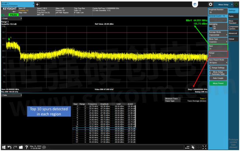
Figure 3 is an example of band n78, where the frequency range is from 3.3 to 3.8GHz, using Keysight's UXA signal analyzers (spectrum analyzers) and PathWave X-Series measurement applications. According to the test requirement, the 1.1 signal transmits at the bottom channel to measure the frequency range below the band, while the top channel measures above the band. The bottom table in this figure shows the top ten spurs detected for each frequency range, so the user can place a marker on the spur of interest to check its frequency and emission level. If all the measured points fall below the limit line, the spurious emission test passes. Otherwise, the failed spurs in the table display appear as a red "F".

Figure 3. An example of a conducted spurious emission measurement of band n78 using Keysight's UXA X-Series signal analyzer (spectrum analyzer)
- +1 Like
- Add to Favorites
Recommend
This document is provided by Sekorm Platform for VIP exclusive service. The copyright is owned by Sekorm. Without authorization, any medias, websites or individual are not allowed to reprint. When authorizing the reprint, the link of www.sekorm.com must be indicated.


