How to Set up an Eye Diagram on an Oscilloscope?

Eye diagrams are extremely helpful in testing the physical layer fidelity of clock or serial data, but many engineers don't know:
What they are
Why they should use one
How to easily set one up
They actually aren't that complex when broken down.
Eye diagrams can quickly give you insight into your signal, along with any jitter or anomalies that may be present that you might know exist.
What they are:
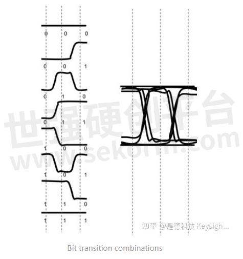
What is an eye diagram? Eye diagrams are a layered view of every bit of transition combination. There are eight of these in total. You can see in Figure 1 how each of these is layered to make up the eye. This provides a composite picture of the overall quality of a system’s physical layer characteristics like amplitude variation, timing uncertainties, or infrequent glitches.
Why you should care
An eye diagram is used to detect jitter,
but what is jitter and why is jitter bad?
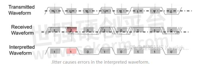
Jitter can cause errors in the data that you are trying to transmit. If there is too much of it riding on your signal, the data that is sent will be interpreted incorrectly by the receiving end because the edge crossings aren’t occurring when they should be.
How to create an eye diagram
One of the first things many people think when they see an eye diagram on an Oscilloscope is “How do you get it to look like that?”
This layered view of bit transitions is not something that a normal trigger would be capable of displaying. The answer is, the oscilloscope utilizes a built-in clock recovery system. Clock recovery is actually pretty straightforward. Some signals have an explicit clock signal, and some have an embedded clock. An explicit clock can be driven right into one of the oscilloscope channels, but embedded clocks have to somehow be de-embedded, or recovered, hence “clock recovery.”
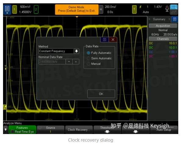
There are three different ways to utilize the clock recovery system, which all depend on how well you know the bitrate of your signal (the width of each bit):
Fully automatic
1. The oscilloscope will calculate the ideal bitrate (or nominal data rate) of your signal.
2. This should be used when you have no idea what the bitrate is and you need the oscilloscope to figure it out.
3. However, this method is only about 80% accurate.
Semi-automatic
1. In most situations, you should have a rough idea of what the bitrate should be. You can very easily make a bitrate measurement on the oscilloscope to find this estimation. This method allows you to enter your rough measurement and then use that information as a seed as it calculates the exact ideal bitrate.
2. This method is significantly more accurate.
Manual
1. This method should be used if you know the exact ideal bitrate of your signal.
2. This is the most accurate method of clock recovery.
There are a few other settings within the clock recovery menu.
To learn more about these, make sure you check out: the video's at the end of this article.
Once you have your clock recovery system set up, all you have to do to set up the eye is press “auto setup”. You will see in just a few seconds that the eye diagram has begun to form. Over time, you will be able to see if there is any jitter or anomalies in your signal. Generally, you will want to let the test run for a longer period of time.
The longer you let it run, the more data is collected, and the more jitter, anomalies, or any infrequent events you can see.
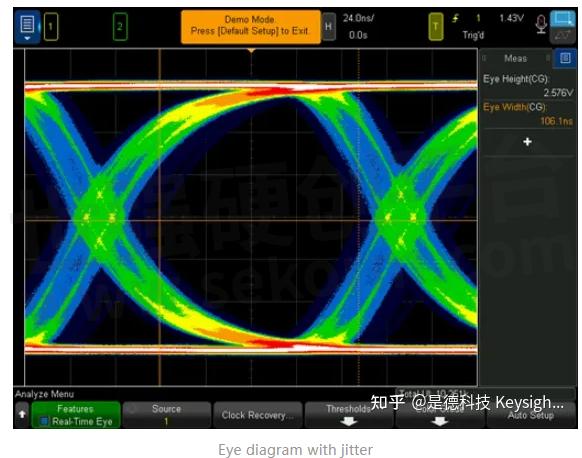
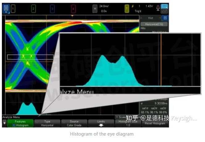
From here, you can analyze the eye diagram further by using the color grading key. This allows you to visually analyze the frequency of each edge crossing. You can also very easily turn on a histogram of the eye to determine whether the jitter is deterministic or random. This will help you decide if this is something you can fix with a phase-locked loop filter or if you have to redesign the component.
- +1 Like
- Add to Favorites
Recommend
This document is provided by Sekorm Platform for VIP exclusive service. The copyright is owned by Sekorm. Without authorization, any medias, websites or individual are not allowed to reprint. When authorizing the reprint, the link of www.sekorm.com must be indicated.


