Heat Sink Selection and Mechanical Criteria

Heat sink selection, taking into account mechanical conditions and requirements other than thermal criteria, is also decisive for the long-term reliable function of devices, modules or systems.
It no longer suffices to restrict heat sink selection to dimensions such as length, width and height. It is equally important for quality assessment purposes, to understand the correlation that decisively influences the overall quality in the design and planning phase.
Heat sinks made of aluminium alloy as extrusion profiles (extruded sections) are partly subject to other criteria than those applicable to pressure die-cast parts or bent metal parts and other conditions must be taken into account during machining. It is therefore often necessary to take this criteria of considerable importance into account during the development phase.
In the total concept of a device, the heat sink is a part that must match different components. It is therefore important during design to take into account that deviations from the nominal dimensions, i.e. tolerances, can be considerable during extrusion. An extruded section is produced by a heated aluminium block, the extrusion billet, being pushed through a tool, the die, with negative shaping of the contour to be produced . ( Photo 1 )
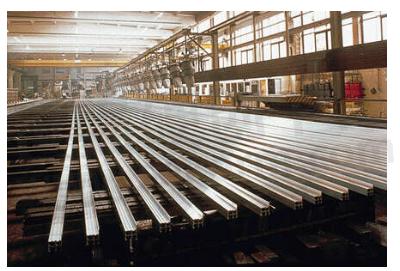
The high deformation forces that occur require correspondingly high section tolerances, so that considerable effort is necessary to minimise these tolerances.
Reference DIN standards define a ± tolerance zone from a few tenths up to several millimetres, depending on the size of the section; not only dimensions such as length, width and height must be taken into account, angular displacement (inclination), distortion and plane-parallelism as well as wall thickness tolerance or curvature of the cross-section are also important assessment criteria. The standards DIN 17615 and 1748 contain exact specifications and it is recommended to become familiar with them.
DIN 17615 is entitled :"Precision profiles of AlMgSi05" and contains the limit deviations for extrusion profiles of sections not exceeding that which can be circumscribed by a circle of 300 mm diameter. DIN 1748 applies to sections greater than 300 mm (Fig. 1).
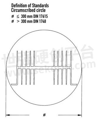
The manufacture of profiles with restricted tolerances results in considerable additional costs due to a lower output per unit of time, and higher discard as a consequence of increased selection expenditure.
The following example clearly illustrates that this expenditure may also have to be taken into account:
According to DIN, the planeness of a heat sink (here, the curvature of the cross-section and linear distortion) to which the components, e.g. IGBT, are screwed, is for example ±1 mm. However, the required planeness for good thermal contact of the IGBT should not exceed ±0.5 mm. Two options are available: a) additional machining (milling) of the profile base produces a planeness of ±0.2 mm and costs the sum of x; b) purchasing a heat sink from a well known manufacturer who produces profiles with a reduced tolerance zone, e.g. half the limit deviations specified in DIN. The profile price a) is less than b), however, profile b) can be used partly or wholly without additional machining and therefore saves considerable costs.
This applies in general and naturally refers also to other limit deviations such as angular displacement, plane-parallelism, etc.
This restricted tolerance zone is of significant importance, for example, also when a heat sink profile is used as an integral part of an enclosure and all aforementioned conditions must contribute to dimensionally and optically perfect function, but milling work is to be avoided. (Fig. 2).
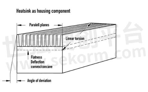
When machining a heat sink , e.g. contour milling, drilling or thread cutting, etc., general tolerances according to DIN 7168 or DIN ISO 2768 apply unless otherwise specified on the drawing; the tolerance class m = medium is used, i.e. DIN 7168.
To clearly illustrate using an example (Fig. 3) it can be shown how the general tolerances from press tolerances and manufacturing tolerances can be favourably structured by appropriate dimensioning.

Shifting the zero point from the outside edge to the profile centre alone can considerably reduce the tolerance band, in this example referenced to the axis of symmetry, by the amount of 1.1 mm. In order to eliminate the deflections of extrusion profiles, the base areas of the heat sink can be milled.
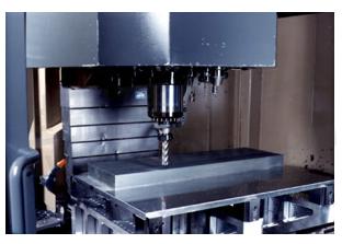
The baseplate becomes thinner with material removal, which must be taken into account in the determination of drilling and thread depths as well as blind holes (Photo 2).
In the example shown (Fig. 4), the baseplate can be up to 0.8 mm thinner than the nominal value after surface milling, since the profile tolerances are 0.2 mm convex (crowned) and 0.8 mm concave (hollow).
Machining according to DIN 74 is shown in the extracts for example:
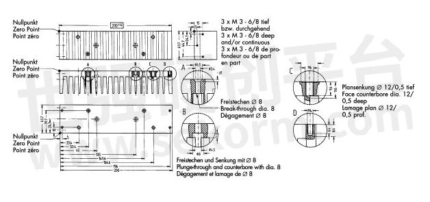
A) Clearance hole according to DIN 74 A m 3, counterbore on base side and fin undercut.
B) Clearance hole with fin undercut according to DIN 74 H m 4 and counterbore from the fin side.
C) Thread M6, thread depth calculated as: Thread dimension multiplied by 1.6 plus 2 mm trepanning depth results in 11.6 mm. Hole at fin base undercut and spotfaced -- 12x0.5 on the base side.
D) Blind thread M4, thread depth 4x1.6 = 6.4 mm plus 2 mm results in a drilling depth of 8.4 mm.
Larger areas on heat sinks must be surface milled in order to achieve good planeness. If the cutter diameter should be smaller than the area to be milled due to the manufacturing process, so-called milling edges appear due to parallel milling.
These are edges in the one thousandth, at a maximum one hundredth millimetre range which normally have no influence on the function of heat transmission or assembly. (Fig. 5).

If these milling paths are to remain invisible, it is practical to specify in the drawing, areas in which no milling edges are required; this requirement is met as far as technically feasible.If these milling paths are to remain invisible, it is practical to specify in the drawing, areas in which no milling edges are required; this requirement is met as far as technically feasible.
The given explanations show that the classification and assignment of press and manufacturing tolerances is unproblematic when the available influencing options are used in a knowledgeable manner. A compilation of selection criteria, based on the area of application of the heat sink enables costs and delivery times to be reduced.
The given explanations show that the classification and assignment of press and manufacturing tolerances is unproblematic when the available influencing options are used in a knowledgeable manner. A compilation of selection criteria, based on the area of application of the heat sink enables costs and delivery times to be reduced.
- +1 Like
- Add to Favorites
Recommend
This document is provided by Sekorm Platform for VIP exclusive service. The copyright is owned by Sekorm. Without authorization, any medias, websites or individual are not allowed to reprint. When authorizing the reprint, the link of www.sekorm.com must be indicated.


