Keysight‘s UXA Signal Analyzers and PathWave X-Series Measurement Applications for 5G NR Base Station Transmit Power Tests
With standards constantly evolving, test solutions must support higher frequencies, wider bandwidths, and new physical layer capabilities. Our daily lives are enhanced by a variety of innovative and comprehensive mobile wireless communication applications thanks to the much faster, more reliable, and near-instant connections that come with the 5G. To ensure that base stations live up to their promises, they must now pass new conformance tests. Conformance testing is an essential part of the base station life-cycle, which requires an in-depth understanding of 3rd Generation Partnership Project (3GPP) specifications. Before a 5G new radio (NR) base station or user equipment (UE) can be released onto the market, it must pass all necessary tests. Unless the products are 3GPP-compliant, they cannot be deployed on networks.

In Release 15, 5G NR is included as well as some new features for long-term evolution (LTE). With Release 16, several new and important enhancements are made to NR, as a first step in the NR evolution, as well as LTE enhancements and extensions. Release 16 introduces two specific sets of features. The first set includes new verticals such as multiple radio access technology (multi-RAT), dual connectivity and carrier aggregation enhancement, industrial internet of things (IIoT), ultra-reliable low latency communications (URLLC), vehicle-to-everything (V2X). This set includes NR unlicensed — NR-U, NR positioning, and a two-step random access channel (RACH). In the second category are features intended to increase capacity and improve operational efficiencies, such as multiple-input multiple-output (MIMO) enhancements, integrated access and backhaul (IAB), cross-link interference / remote interference management, user equipment (UE) power savings, and mobility enhancements.
Throughout this blog series, we'll discuss the key conducted and radiated transmitter tests for frequency range (FR)1 and FR2 base stations, the testing challenges, and the most advanced industry solutions to meet them for accurate and reliable results. In part 1, we will discuss the transmit power tests and requirements.
Conformance Testing of 3GPP Base Stations
3GPP defines radio frequency (RF) conformance test methods and requirements for NR base stations in TS 38.141, covering transmission, reception, and performance tests. Depending on whether the test methodology has conducted or radiated requirements, this technical specification comprises two parts. Part 1 of TS 38.141-1 focuses on conducted conformance tests, while part 2 of TS 38.141-2 covers radiated conformance tests in both frequency ranges (FR) 1 and FR2 in accordance with the base station type. A summary of base station conformance tests for conducted and radiated situations can be found in Table 1.
A base station can be configured in one of four ways, depending on whether the tests are conducted or radiated, and the configuration of the station. Type 1-C refers to NR base stations operating at FR1 with requirements at individual antenna connectors. A Type 1-H NR base station operates at the first frequency range (FR1), with requirements defined at the individual transceiver array boundary (TAB) connectors and over-the-air (OTA) requirements defined at the radiated interface boundary (RIB). The two types of O bases refer to NR base stations that operate at FR1 or FR2 and are required to meet only the OTA constraints defined by the RIB. The main difference between conducted and radiated tests is the radiated tests for base station types 1-H, 1O, and 2O.
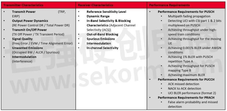
Table 1. Release 16 base station conducted and radiated conformance tests
Test Requirements for Base Station Transmitters
Your 5G NR measurement application on your signal analyzer should be able to measure the required tests specified by standards as well as those covered by the 5G NR application. Channel power and occupied bandwidth are among the most common tests, along with adjacent channel leakage ratio (ACLR), operating band unwanted emissions (OBUE), spurious emissions, Tx on/off power, error vector magnitude (EVM), frequency error, and time alignment error (TAE). There are a number of transmitter characteristics and the test measurements covered in standards as well, such as output power, output power dynamics, transmit on / off power, transmit signal quality, unwanted emissions, and transmitter intermodulation.
Measurements of Output Power Dynamics
Testing output power is performed to determine how accurate the power output is in comparison with the base station's declared value when transmitting at maximum power. The measurement result shown in Figure 1 (left) was obtained on a 100 MHz bandwidth time division duplex (TDD) signal with a measurement mode of channel power. The gate start and stop lines indicate the part within the frame used to measure power. Over the 100 MHz bandwidth, power was measured at -1.04 dBm, while the transmitted signal was at 0 dBm. Cable loss is pre-calibrated at 0.64 dB. Power accuracy is estimated at -0.4 dB, which is within the test requirements.
Output power dynamics refers to the differences in power levels when a base station transmits at maximum and minimum levels. Measurements should be made on orthogonal frequency division multiplexing (OFDM) symbols that carry only physical data shared channel (PDSCH) data, without any synchronization signal block (SSB) or demodulation reference signal (DMRS) within the symbol. The OFDM symbol transmit power limit (OSTP) is measured only for data symbols and is a requirement for dynamic power measurement.
Keysight's UXA signal analyzers and PathWave X-Series measurement applications are used to measure the output power dynamics in Figure 1 (right). OSTP measurement results are -1.02 dBm for maximum transmit power from the base station. It can be measured using test model 3.1, which can be selected from a list of test models. Following successful demodulation of the signal, the OSTP and other measurement results will be displayed on the display.
Test model 3.1 is a full resource block (RB) allocation with 64QAM modulation, as can be seen in the multiple traces display. You can also measure the minimum power using test model 2 signal with a single RB. Therefore, you can calculate the power dynamic of 25.48 dB and compare it with the standard requirements.

Figure 1. An example of conducted output power measurement test model (left) and the output power dynamics (right)
Measurement of Transmit Power On and Off
By testing the transmit off power, we can ensure that it is within limits defined by the standard. However, this test is applicable only to base station systems operating in TDD mode. The definition is the mean power measured over 70 / N µs filtered with a square filter of bandwidth equal to the transmission bandwidth configuration of the base station, centered on the assigned channel frequency during the transmit off period (N = SCS / 15), and SCS is subcarrier spacing in kHz.
Two technical aspects need to be verified in this test: One is to measure the power level when the transmitter is off and check it against the requirement for passing or failing. The other is to measure the transient time, ramp-up time, and ramp-down time of a burst of the TDD signal. An off power value should be less than about -83 dBm / MHz for a conducted test and -102 dBm / MHz for a radiated test.
Transient time is the time that the transmitter can go from off to on power level and vice versa. In Figure 2, Keysight's UXA signal analyzers and PathWave X-Series measurement applications are used to measure the transmit off / on power and transient times for 5G NR. An external trigger determines the burst boundary in this example. Using the frame structure of the test model, the power ramp up and down can be used to measure the transient time.
The power envelope mask indicates the expected limit of off power as well as ramp-up and ramp-down positions. In the metrics table at the bottom are the measurements for the transmit on power, off power, ramp up, and downtime. Results are displayed in the top left corner in the form of a pass/fail indicator, so you can compare them with the defined standards. These limits are set to 3GPP specifications by default, but you can modify them to suit your particular testing needs.

Figure 2. An example of conducted transmit on / off power measurement
As With standards evolving, test solutions must support higher frequencies, wider bandwidths, and new physical layer features. When you plan your next steps for design and innovation in 5G, understanding the standards and how they impact testing is crucial to ensuring successful and accurate testing.
- +1 Like
- Add to Favorites
Recommend
- Keysight Technologies Acquires Quantum Benchmar, Augmenting Keysight‘s Quantum Portfolio
- Keysight First to Gain GCF Approval of Cases for Validating 5G New Radio mmWave Devices in Standalone Mode
- Keysight‘s O-RAN Test Solutions Enable Xilinx to Accelerate Development of Massive MIMO Radio Reference Design
- Keysight and Transphorm Create Power Supply Reference Design that Lowers Product Costs; Speeds Time to Market
- Keysight Massively Parallel Board Test System Selected by LACROIX in Automotive Printed Circuit Board Manufacturing
- Keysight, TIM and JMA Wireless Join Forces to Showcase O-RAN Technology at Mobile World Congress 2021
- Keysight First to Gain OmniAir Qualified Test Equipment Status, Accelerating C-V2X Device Certification
- Keysight Delivers New Solution for Benchmarking 5G End-user Quality of Experience in Indoor Environments
This document is provided by Sekorm Platform for VIP exclusive service. The copyright is owned by Sekorm. Without authorization, any medias, websites or individual are not allowed to reprint. When authorizing the reprint, the link of www.sekorm.com must be indicated.
Integrated Circuits


Discrete Components


Connectors & Structural Components


Assembly UnitModules & Accessories


Power Supplies & Power Modules


Electronic Materials


Instrumentation & Test Kit


Electrical Tools & Materials


Mechatronics


Processing & Customization


