How to effectively prevent or reduce the impact of thermal deformation of battery tray welding?

Battery trays, also known as battery boxes or PACK boxes, are increasingly valued as a very important component in the development of new energy vehicles. The design of Battery trays needs to balance the relationship between factors such as weight, safety, cost, and material performance. Aluminum alloys are widely used in automotive lightweight engineering because of their low density and high specific strength, which can ensure rigidity while ensuring vehicle body performance.
1-Battery tray welding location and method selection
Aluminum battery trays are made of extruded aluminum profiles, and the various components are combined into a whole by welding to form a complete frame structure. Similar structures are also widely used in energy storage pack boxes.
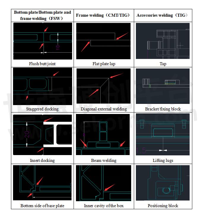
The welding parts of the battery tray usually include the bottom plate splicing, the connection between the bottom plate and the side, the connection between the side frame, the horizontal and vertical beams, the welding of liquid cooling system components, and the welding of accessories such as brackets and hanging ears. When selecting welding methods, different welding methods will be selected according to different material and structural requirements, see the table below:

2-Analysis of the influence of welding thermal deformation
Welding is a local heating processing method. Since the heat source is concentrated at the weld, the temperature distribution on the weld is uneven, which eventually leads to welding deformation and welding stress inside the welded structure. Welding thermal deformation is the phenomenon that the shape and size of the welded parts change due to uneven heat input and heat output during the welding process. Combined with actual engineering project experience, the parts that are prone to welding thermal deformation and the influencing factors are summarized:
a. Long straight welding area
In actual production, the bottom plate of the battery tray is generally made of 2 to 4 aluminum alloy profiles spliced together by stir friction welding. The welds are long, and there are also long welds between the bottom plate and the side plate, and between the bottom plate and the spacing beam. Long welds are prone to local overheating in the welding area due to concentrated heat input, resulting in thermal deformation.

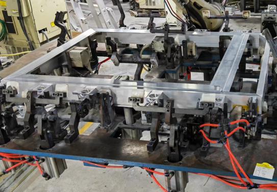
Battery tray frame welding
b. Multi-component joints
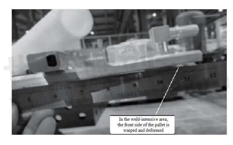
It is caused by local high temperature heating and subsequent cooling during the welding process at the multi-component weld. During the welding process, the weldment is subjected to uneven heat input, resulting in a significant temperature difference between the weld area and the surrounding parent material, which causes thermal expansion and contraction effects, causing deformation of the welded parts. The electrical installation end of the energy storage pack box is usually equipped with a water nozzle, a wiring harness bracket, a beam, etc., and the welds are dense and very easy to deform.

In the weld-intensive area, the front side of the pallet is warped and deformed
c.Cold plate channel side wall
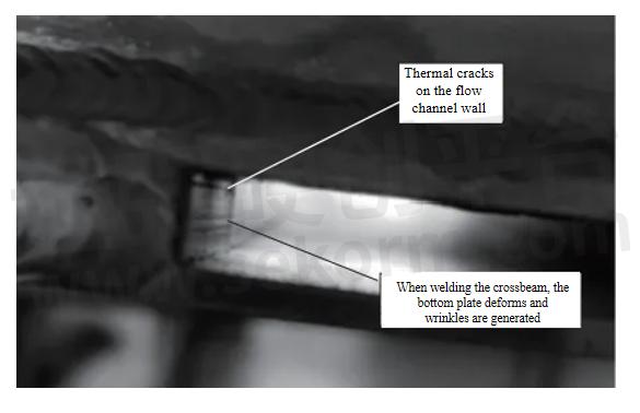
In the battery tray with integrated design of liquid cooling plate, parts with smaller structural rigidity, such as thin plates and pipe structures, cannot resist thermal deformation well during welding and are prone to deformation. For example, the side wall of the liquid cooling plate flow channel is very thin, generally only about 2mm. When welding beams, wiring harness brackets and other parts on the module mounting surface, it is easy to cause cracks and deformation wrinkles on the side wall of the flow channel, affecting the overall performance.

Thermal crack defects on the liquid cooling channel wall caused by beam welding
3-Welding thermal deformation control method
a. Segment welding, double-sided welding
For parts with relatively low strength requirements, segmented welding is adopted, and the welding process is broken down into multiple small sections. The welds are arranged symmetrically, and the welds are arranged symmetrically near the neutral axis in the construction section, so that the deformations caused by the welds may offset each other. At the same time, the length and number of welds are minimized, and excessive concentration or crossing of welds is avoided, which can reduce the welding temperature gradient and thus reduce welding deformation. For parts with high strength requirements such as the bottom plate, bottom plate and side frame, double-sided welding is adopted to increase strength while reducing bending deformation caused by large parts and long welds.
b.Optimizing welding sequence
Control welding deformation, use joints with lower rigidity, avoid two-way and three-way intersecting welds, and avoid high stress areas. Optimize the welding sequence, weld the weaker rigidity areas first, and the better rigidity areas last, such as welding the fillet welds first, then the short welds, and finally the long welds; weld the transverse welds first, then the longitudinal welds. A reasonable welding sequence can effectively control welding deformation, thereby controlling the weld dimensions.
c.Welding parameter adjustment
Control welding parameters and processes, and reasonably set welding speed, number of welding layers and thickness of each weld. For thicker welds, use multi-layer and multi-channel welding methods, and the thickness of each weld layer should not exceed 4mm. Multi-layer welding can reduce structural microstructure and improve joint performance. Accurately control welding parameters and reasonably select parameters such as welding current, voltage, electrode model and welding speed to ensure consistent shape and size of the molten pool, thereby avoiding errors caused by improper parameter selection.
d.Welding skills improvement
Improve the welder's operating skills (use mechanical processing for large components or nodes with strict requirements) to ensure consistency and standardization of actions during welding and reduce dimensional problems caused by human factors.
- +1 Like
- Add to Favorites
Recommend
This document is provided by Sekorm Platform for VIP exclusive service. The copyright is owned by Sekorm. Without authorization, any medias, websites or individual are not allowed to reprint. When authorizing the reprint, the link of www.sekorm.com must be indicated.


