EPC GaN ICs Simplify Motor Joint Inverter Design for Humanoid Robots

Battery-powered applications such as new-generation robots, drones, and power tools require a reduction in space and a simplification of the design to control electric motors. Optimizing size and components results in innovative solutions that include more functions in a small space without losing efficiency and performance. EPC ePower™ Stage ICs technology helps to simplify and improve the inverter design in advanced motor control applications.By Francesco Musumeci, Application Engineer, Italy Application Center, Efficient Power Conversion
June, 2024
In inverters for low voltage motor drive applications [1], GaN technology brings crucial improvements such as the switching frequency increase, the reduction of the passive component in the converter input filter (capacitors and inductors), the strong dead-time decrease with the improvement of the output current waveform quality, and the high-power density which contributes to the overall reduction of the converter size. The introduction of monolithic integrated circuits (ICs) in full GaN technology, composed of a switching leg power stage, a half-bridge gate driver with bootstrap supply, and several protection circuits, simplifies the converter’s design and allows a noticeable volume reduction. Innovative applications such as motor joints for humanoid robots are significantly improved by motor drive inverters using EPC’s monolithic integrated devices because they result in more compact and lighter converter; moreover, the inverter runs cool thanks to their superior efficiency performance and low switching losses of the GaN devices as well as reduction in motor losses by the higher quality of the driving waveforms.
This article introduces the latest generation of GaN integrated circuits (EPC23102/3/4) [3, 4, 5] for inverter applications. Several evaluation boards with new features, discussed in the following sections, have been developed to demonstrate the effectiveness of implementing ICs in inverter performance. In particular, the ICs’ temperature versus the motor phase current will be reported and discussed.
GaN advantage
The critical field in a semiconductor material determines the breakdown voltage of a device. For a given breakdown voltage, the higher the electric field, the shorter the width of the drift region. In a GaN transistor, the critical field is an order of magnitude higher than silicon, and the electron mobility due to the two-dimensional electron gas (2DEG) makes the ON resistance low while keeping its dimensions small [2].
GaN technology is based on a planar layout. In reverse conduction, a GaN transistor features an equivalent body diode with no reverse recovery charge (QRR = 0). Furthermore, GaN devices have parasitic capacitances approximately an order of magnitude lower than their silicon counterparts for a given ON resistance. Smaller parasitic capacitances lead to higher switching capability, higher PWM frequency, and minimum dead time for improved motor efficiency.
EPC2310x:
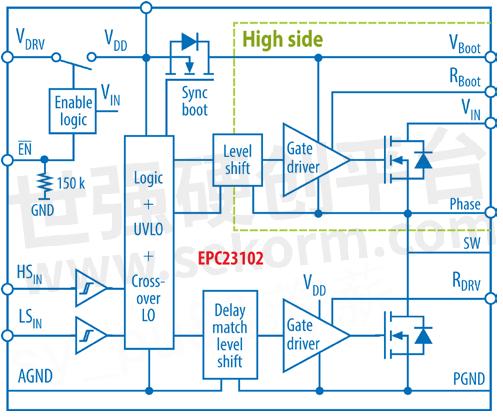
ePower™ Stage IC Features The ePower™ Stage IC product family integrates input logic interface, high-side level shifting gate driver, and synchronous bootstrap supply, together with eGaN output FETs into one monolithic integrated circuit using EPC’s proprietary GaN IC technology; these devices are packaged in a 3.5x5mm FCQFN package. The new generation of Efficient Power Conversion monolithic integrated circuits is composed of three 100V-rated products. The three ICs (EPC23102/3/4) differ in the ON-resistance (RDS,ON) of the power FETs, allowing the devices to be used in different applications. EPC23102 is the lower RDS,ON device with 6.6mΩ max for high and low side FETs [3], followed by the EPC23103 with 7.7 mΩ max. and the EPC23104 with 11mΩ max. [4][5]. The devices’ structure is described in the block diagram circuit of Figure 1.

Figure 1: EPC23102/3/4 functional block diagram
Reference designs
EPC has released several reference design boards for motor drive inverters using GaN FETs discrete and GaN integrated circuits. All reference design boards share a similar block diagram and controller connector to help the designer scale the current and voltage during the inverter’s platform design phase.
Integrated circuit-based motor drive applications allow for smaller boards and easier design. The new version of the EPC9176 [6] and the new EPC91103 [7] and EPC91104 [8] boards show an example of the simplification and space reduction of a motor drive inverter. The evaluation boards have the same layout but differ in the power stage and the type of phase current sensor. The EPC9176 is equipped with the EPC23102, the EPC91103 mounts the EPC23103, and the EPC91104 mounts EPC23104 devices.
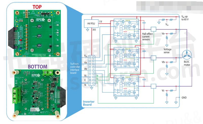
The new reference design boards measure 7.5 x 7.2 cm. The inverter input voltage ranges from 14 V to 85 V. The PCB stackup structure comprises an 8-layer FR4 PCB with 2oz on the top, bottom, and 4oz inner layers to reduce the PCB conduction resistance and to have a better heat spreading thanks to the thicker copper. The boards comprise auxiliary power supplies to generate 5V and 3.3V from the DC Bus, phase voltage sense, phase current halleffect sensors, hall/encoder interface for sensored control, and over-current protection circuit as shown in Figure 2.
The most important feature of the reference boards is the simplification of the inverter design, particularly on their top side. As shown in the layout in Figure 2, only the power devices and their respective hall-effect phase current sensors are mounted on the PCB top surface. This facilitates heat spread from the power devices and a better interface with the heat sink mounted on the top. All other components related to analog sensing signals, power supply, and over-current have been placed on the bottom side of the board. The DC-link is composed of ceramic capacitors placed on the top and bottom side of the board, connected to the DC-Bus connector and power devices with alternate tracks of the input voltage VIN and GND also repeated in the internal layers for a better distribution of the DC-Bus current in the layers.
The hall effect current sensors mounted in the new reference boards permit reducing the complexity of the current sensing circuit. The Hall-based phase current sensing solution does not need external conditioning circuits and compared to conventional solutions with shunt resistors, further simplifies the motor drive inverter board design.

Figure 2: EPC9176 Rev3.0 top and bottom views with system block diagram
Experimental results
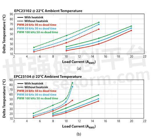
Steady-state operation tests with and without heat sink with no forced air cooling are shown in Figure 3 and describe the thermal behavior of the EPC9176 and EPC91104 boards. With a 48 VDC DC Bus, The EPC23102 mounted on EPC9176 can continuously carry 15ARMS motor phase current without a heatsink, showing a temperature increase of device die with respect to the ambient temperature less than 75℃ for switching frequencies up to 100kHz and 50ns dead time. The EPC9176, with a heatsink under passive air cooling (no forced convection), can sustain 20ARMS with a temperature increase of 65℃ for switching frequency up to 100kHz and 50 ns dead time.
The EPC23104 mounted on EPC91104 presents a different thermal behavior due to the different devices RDS,ON. The EPC23104 can reach 10ARMS without a heatsink and 15ARMS with a heatsink and passive air cooling, with die temperature increase below 60℃, switching frequency up to 100kHz, and 50ns dead time.
Conclusion
Gallium nitride-based Integrated circuits from EPC innovate motor drive inverters. The use of logic-in power-out integrated circuits makes design easier and reduces the dimension of the inverter ensuring greater compactness and weight reduction. Thanks to higher switching frequency, ohmic losses in the motor are reduced, the input filter size is reduced, and the overall system efficiency is increased with a decrease of system-generated heat; shorter dead time allows for silent operation and improves motor performance. Smaller size, less heat generation, and more compactness allow for the realization of inverters integrated into the motors, which are perfect for applications such as humanoid robot joints.

Figure 3: a) EPC3102 and b) EPC23104 temperature rise as function of motor phase current and PWM frequency
References
[1] A. Lidow, GaN Power Devices and Applications. Chapter 6, First Edition, Power Conversion Publications. ISBN 978-0-9966492-2- 3
[2] A. Lidow, M. De Rooij, J. Strydom, D. Reusch, J. Glaser, GaN Transistors for Efficient Power Conversion. Third Edition, Wiley. ISBN 978-1-119-59414-7
[3] https://epc-co.com/epc/products/gan-fets-and-ics/epc23102
[4] https://epc-co.com/epc/products/gan-fets-and-ics/epc23103
[5] https://epc-co.com/epc/products/gan-fets-and-ics/epc23104
[6] https://epc-co.com/epc/products/evaluation-boards/epc9176
[7] https://epc-co.com/epc/products/evaluation-boards/epc91103

- +1 Like
- Add to Favorites
Recommend
This document is provided by Sekorm Platform for VIP exclusive service. The copyright is owned by Sekorm. Without authorization, any medias, websites or individual are not allowed to reprint. When authorizing the reprint, the link of www.sekorm.com must be indicated.


