DEMO kit tutorial of LoRa module LoRa1262

1. Introduction to the DEMO kit of the LoRa module LoRa1262
The LoRa module LoRa1262 is our hot-selling product, and its core chip adopts the SX1262 radio frequency chip of Semtech. The LoRa1262 wireless module antenna switch is integrated and controlled by the chip, which saves the resources of the external MCU. The working frequency band is: 433/470/868/915 MHz.
2. The function description of the DEMO kit of the LoRa module LoRa1262
The DEMO kit of LoRa module LoRa1262 cooperates with our sample program, which can easily observe the SPI communication between the MCU and the wireless module, and can use this development board as a standard signal source without professional RF instruments to debug the customer's development. Program, can greatly shorten the product development cycle of software engineers. Parameters such as frequency band, power, bandwidth, speed, etc. of the wireless module can be set in the demo board.
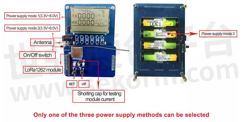
3. Button description of DEMO kit of LoRa module LoRa1262
There are two buttons on the DEMO kit, namely: SET button and UP button.
ButtonFunctionSET buttonPress the key to enter the setting mode. If you set the last parameter, press the key to exit the setting mode.UP buttonIn the setting mode, press the key to modify the corresponding setting parameters.
4. The operation method of the DEMO kitof the LoRa module LoRa1262
Normal power supply, toggle the power switch, the main interface will appear on the LCD screen of the DEMO kit, and the main interface will display parameters such as TX, RX, FREQ, PWR, CR, SF, BW, etc. Among them, TX and RX represent the LoRa1262 LoRa module communication is to transmit and receive data packets, which cannot be set and modified. FREQ, PWR, CR, SF, and BW are frequency band, power, coding rate, propagation factor and bandwidth, respectively. The setting method is as follows: SET key to select the parameter that needs to be modified, such as modifying power, SET key to select PWR, up key to adjust the power size, the power selection range is: 0-9, press the SET key to confirm the adjustment parameter, it will jump to the next need Modify the parameters, and the power parameters are modified at the same time. (Note: with FLASH inside, all the set parameters can be saved when power off.)
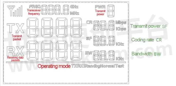
(LoRa1262 DEMO kit LCD interface analysis diagram)
At the bottom of the main interface is the working mode. There are five working modes, RX-Normal, TX-Normal, TX-test, RX-test and standby. Among them, RX-Normal and TX-Normal are receiving mode and transmitting mode respectively, TX-Normal, TX-test, RX-test are test modes, and standby is sleep mode. Modify the operation mode as follows: SET key to enter the working mode, UP key to select the working mode, and finally press the SET key to confirm the working mode. If you do not need to modify the working mode, press the SET key to skip.
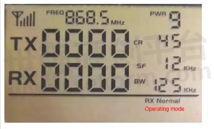
(Main interface working mode location map)
5. The communication test method of the DEMO kit of the LoRa module LoRa1262
①Prepare two LoRa1262 DEMO kits
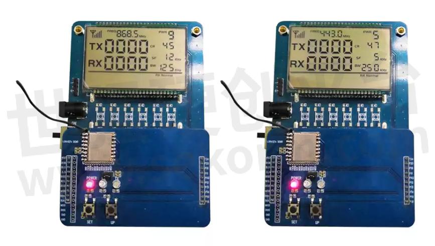
②Set the DEMO kit parameters of the two LoRa modules LoRa1262 to be the same.

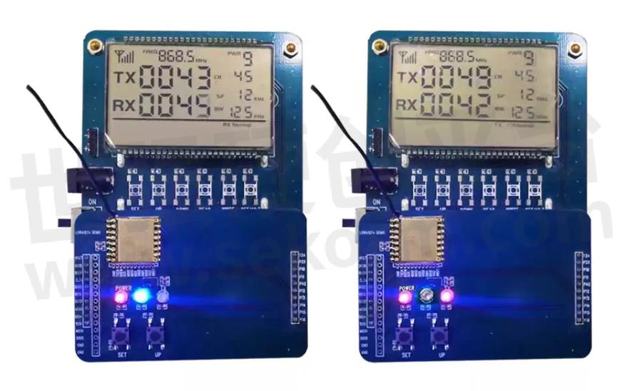
③Set the working mode of the DEMO kit of one LoRa1262 to: RX-Normal, and set the other working mode to: TX-Normal. At this time, observe the TX and RX on the LCD screen, and the numbers appear to increase continuously, indicating that the communication is successful. (The red indicator light represents a successful transmission, and the blue indicator light represents a successful reception) as shown in the figure:
- +1 Like
- Add to Favorites
Recommend
This document is provided by Sekorm Platform for VIP exclusive service. The copyright is owned by Sekorm. Without authorization, any medias, websites or individual are not allowed to reprint. When authorizing the reprint, the link of www.sekorm.com must be indicated.
Integrated Circuits


Discrete Components


Connectors & Structural Components


Assembly UnitModules & Accessories


Power Supplies & Power Modules


Electronic Materials


Instrumentation & Test Kit


Electrical Tools & Materials


Mechatronics


Processing & Customization


