Application of Diode MOS in Electric Two-wheeled Vehicle

Recently, a large electric vehicle factory launched a two-wheeled electric vehicle, which became a hot topic for a time. China is the world's largest producer and consumer of two-wheeled electric vehicles, accounting for more than half of the global sales. With the continuous maturity of the electric two-wheeled vehicle scheme, the industrial support is more perfect, the product performance continues to improve, and the price is more reasonable. What is the working principle of the electric two-wheeled vehicle? What is the application of triode MOS in electric two-wheeled vehicles? In this issue, Hottech takes you familiar with the work and internal structure of electric vehicles.
Structure and working principle of electric two-wheeled vehicle
The structure of electric two-wheeled vehicle is relatively simple, which consists of motor, battery, control system, braking system, wheels and auxiliary components, and usually includes the following main parts:

1. Motor: A motor is the power source of an electric two-wheeled vehicle, usually installed near the rear wheel. The most common motor is the DC brushless motor, which has the characteristics of high efficiency, low noise, and long service life.
2. Battery: The battery is an energy storage device of an electric two-wheeled vehicle, which is usually installed at the bottom of the frame or under the seat. There are mainly two types of batteries: lead-acid batteries and lithium batteries, among which lithium batteries have higher energy density and longer life, but the cost is relatively high.
3. Control system: The control system is one of the core components of the electric two-wheeled vehicle, which is responsible for controlling the operation of the motor and the running state of the vehicle. A control system usually includes a controller, a sensor and a circuit, wherein the controller is responsible for receiving the instructions of the rider and controlling the operation of the motor, and the sensor is used for monitoring the speed, position and other parameters of the vehicle and feeding back the information to the controller.
4. Braking system: The braking system is one of the safety guarantees for electric two-wheeled vehicles. It is responsible for braking and decelerating during the running of the vehicle, and usually includes components such as brakes, brake pads and brake lines, in which the brakes are responsible for generating braking torque, while the brake pads contact with the wheels to generate friction, thus realizing the braking and decelerating of the vehicle.
5. Wheels, frames and tires: Wheels and tires are important parts of electric two-wheeled vehicles. They are in direct contact with the ground and bear the weight of the vehicle and the friction when driving. Wheels are usually composed of hubs, spokes and tires, while tires are made of rubber. The frame is the basic structure of the electric two-wheeled vehicle, which supports the weight of the whole vehicle and connects all the components.
6. Auxiliary components: In addition to the above components, the electric two-wheeled vehicle also includes some auxiliary components such as seats, pedals, mirrors, headlights and speakers.
Usually, it works like this. Its drive and control system is mainly composed of battery pack, motor, controller and speed control handle. The current in the battery pack is modulated and demodulated by the speed control handle and controller to supply power to the motor, so as to control the motor speed to drive the car to run. The current of the battery pack is supplied to the controller, and the step-down device in the controller supplies power to the speed-regulating handle. Rotating the speed-regulating handle allows the controller to detect different voltage values, and the controller simulates and adjusts the voltage delivered to the motor according to the voltage values, thus controlling the speed of the motor and the running speed of the electric vehicle.
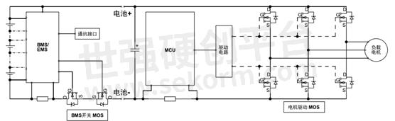
Usually, there are several kinds of BMS architectures for electric two-wheeled vehicles, some of which are different in that the charging and discharging MOS is placed on the high side or the low side, and some are different in that the charging and discharging are connected in series or in parallel. At present, many BMSs of two-wheeled vehicles on the market use bottom-side series architecture, and the driving circuit is relatively simple. The mainstream BMS architecture of electric two-wheeled vehicles in the market consists of main control, battery, secondary protection and analog front end. This is double protection by using AFE to control the on-off of MOS tube and secondary protection chip to control the three-terminal FUSE. The electric drive system is a highly integrated and intelligent system, which converts the electric energy in the battery into mechanical energy to drive the vehicle forward, and optimizes the performance and safety of the vehicle through various sensors and control systems. Usually, the traditional H6 bridge is used in the electric drive of most electric two-wheeled vehicles in the market, and the FOC control mode is the mainstream, which has the characteristics of small torque fluctuation, high efficiency, low noise and fast dynamic response.
Application of Diode MOS in Electric Two-wheeled Vehicle
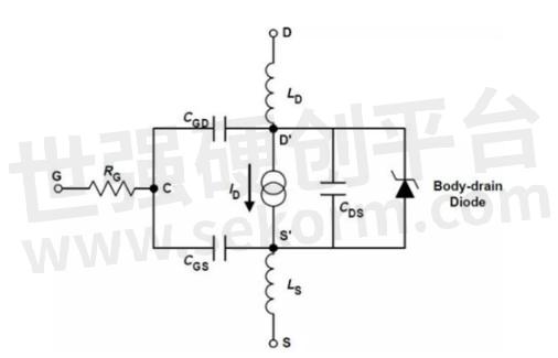
Take MOS tube as an example, its function in electric vehicle controller is switching and voltage regulation. Simply put, the motor is driven by the output current of MOS tube. The larger the output current is, the controller usually limits the current protection to prevent the MOS tube from being burnt by overcurrent, so that the motor torque is strong and the acceleration is powerful. Because the driving power of motor is generally more than 100 watts, MOS Transistor driver and external MOSFET are widely used in the industry to improve the heat dissipation capacity. Because there is back electromotive force in the motor, this back electromotive force will be superimposed on the battery pack voltage and directly act on the MOSFET during deceleration, so a certain margin should be reserved for the withstand voltage of the MOSFET and the corresponding driver.
The working state of MOS tube in the controller circuit is as follows: on process, on state, off process, off state and breakdown state. The main losses of MOS transistor include switching loss (turn-on process and turn-off process), turn-on loss, turn-off loss (caused by leakage current, which is neglected), and avalanche energy loss.
As long as these losses are controlled within the tolerance specifications of MOS tubes, MOS tubes will work normally, and if they exceed the tolerance range, they will be damaged. However, the switching loss is often greater than the on-state loss, especially when the PWM is not fully turned on and in the pulse width modulation state, which corresponds to the starting acceleration state of the electric vehicle, and the highest rapid state is often dominated by the on-state loss.
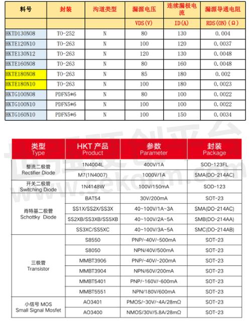
Hottech's products used in the whole electric two-wheeled vehicle include diodes, triodes and MOS tubes, which play a role in switching, rectifying, amplifying and stabilizing voltage in the circuit. Welcome to consult Hottech for specific products.
- +1 Like
- Add to Favorites
Recommend
- Review of Hottech Munich (Shanghai) Electronics Show
- Great News: Hottech Won The Invention Patent Certificate for “a High-frequency and High-current Rectifier“
- A Professional Splitters Manufacturer Hottech Appeared at Shenzhen International Semiconductor Exhibition
- Guangdong Hottech Industrial Co., Ltd. Won the National “High-tech Enterprise“ Recognition
- Shenzhen Hottech Won The Recognition of Specialized, Special and Innovative SMES in 2022
- Application of Hottech NMOS Products in Electric Two-wheeled Vehicles
- Hottech‘s “Linear Lithium-ion Battery Charging Management Chip“ Won The National Invention Patent Certificate
- Hottech Is Invited to Attend Inatronics at 2024
This document is provided by Sekorm Platform for VIP exclusive service. The copyright is owned by Sekorm. Without authorization, any medias, websites or individual are not allowed to reprint. When authorizing the reprint, the link of www.sekorm.com must be indicated.
Integrated Circuits


Discrete Components


Connectors & Structural Components


Assembly UnitModules & Accessories


Power Supplies & Power Modules


Electronic Materials


Instrumentation & Test Kit


Electrical Tools & Materials


Mechatronics


Processing & Customization


