Slkor BZT52C5V6S: Precision Zener Diode for Voltage Regulation with A VZTyp rating of 5.6V and A Maximum Power Dissipation of 200mW

The BZT52C5V6S is a precision Zener diode engineered for reliable voltage regulation in electronic circuits. With a VZTyp rating of 5.6V and a voltage range (VZ) of 5.2V to 6V, this diode ensures stable and accurate voltage output. Additionally, with a maximum power dissipation (PD) of 200mW, an ultra-low reverse current (Ir) of 1μA at 2V, and a dynamic impedance (Zzt) of 40Ω, it offers efficient operation and improved performance.

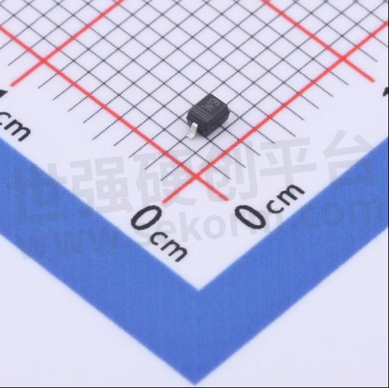
SLKOR Voltage Regulator Diode BZT52C5V6S product photo
Key Points:
Precision Voltage Regulation:
VZTyp rating of 5.6V ensures accurate voltage output within a specified range (VZ: 5.2V to 6V).
Efficient Power Handling:
PD rating of 200mW allows for effective dissipation of power, enhancing the diode's performance.
Ultra-Low Reverse Current:
Ir of 1μA at 2V minimizes power loss, contributing to improved efficiency and reliability.
Dynamic Impedance:
Zzt of 40Ω indicates the diode's ability to maintain stable voltage output under varying conditions.

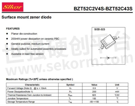
Slkor Zener diode BZT52C5V6S specification

Parameters of Slkor Zener diode BZT52C5V6S
Voltage Divider Circuit with Zener Diode
The voltage divider circuit with a Zener diode is a widely used circuit in electronic devices. It utilizes the voltage regulation characteristics of a Zener diode to distribute the input voltage steadily to one or more output terminals. Below is a detailed overview of the voltage divider circuit with a Zener diode:
Circuit Components
The voltage divider circuit with a Zener diode mainly consists of components such as the Zener diode, current-limiting resistor, and load resistor. The Zener diode, being the core component of the circuit, stabilizes the output voltage. The current-limiting resistor restricts the current in the circuit, safeguarding the Zener diode and other components from damage. The load resistor serves as the output terminal of the circuit, connecting to electronic devices requiring a stable voltage.
Working Principle
● Voltage Distribution: In the voltage divider circuit with a Zener diode, the input voltage is first divided by the current-limiting resistor, creating two or more branches with different voltages. The distribution of these branch voltages depends on the resistance ratio.
● Role of the Zener Diode: Within each branch, the Zener diode is connected in parallel across the load resistor. When the input voltage changes, the Zener diode utilizes its voltage regulation characteristics to stabilize the voltage across the load resistor near its nominal value. This is achieved by maintaining nearly constant terminal voltage across the Zener diode within a certain range of reverse breakdown.
● Role of the Current-Limiting Resistor: The current-limiting resistor restricts the current in the circuit. It determines an appropriate range of resistance values based on the Zener diode's minimum and maximum stable currents, as well as the resistance value of the load resistor. This ensures that the Zener diode operates normally within its regulation region and does not exceed its rated power.
Design Considerations
● Selecting the Right Zener Diode: Choose a suitable Zener diode model according to the circuit's output voltage requirements. For example, the BZT52C5V6S Zener diode has a nominal voltage of 5.6V, suitable for circuits requiring a stable output voltage of 5.6V.
● Calculating the Resistance Value of the Current-Limiting Resistor: Calculate the resistance value range of the current-limiting resistor based on the Zener diode's minimum and maximum stable currents, as well as the resistance value of the load resistor. Ensure the Zener diode operates normally within its regulation region and does not exceed its rated power.
● Consider Circuit Stability: When designing the circuit, consider factors such as stability, power consumption, and efficiency. For example, optimizing the resistance ratio and selecting low-power components can reduce circuit power consumption and improve efficiency.
Examples of Applications
The voltage divider circuit with a Zener diode finds extensive applications in electronic devices. For instance, in power supply circuits, it can distribute the input voltage steadily to various functional modules. In signal processing circuits, it can provide a stable reference voltage for analog circuits. In surge protection circuits, it can function as an overvoltage protection device.
- +1 Like
- Add to Favorites
Recommend
This document is provided by Sekorm Platform for VIP exclusive service. The copyright is owned by Sekorm. Without authorization, any medias, websites or individual are not allowed to reprint. When authorizing the reprint, the link of www.sekorm.com must be indicated.


