Understand the N and P MOS Operation of MOSFETs

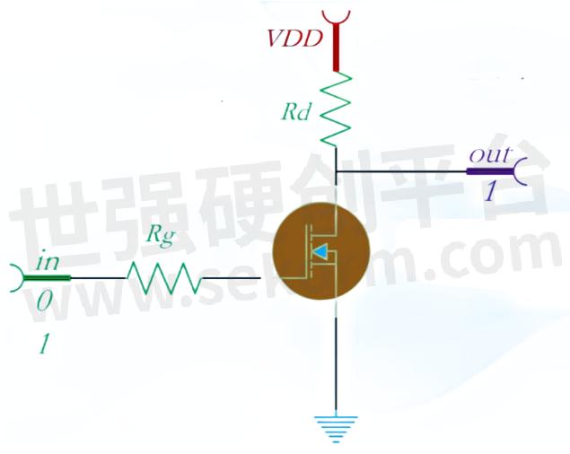
In the early days, only N MOS was supported to achieve logical functions. Nowadays, N MOS and P MOS are used because the MOS transistor occupies a much smaller area than the resistor and has a higher amplification factor! This is a typical non gate circuit, and the current flowing through the MOS transistor will be very large.

Fig.1
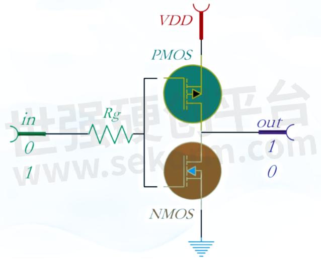
When high voltage is input, the current flowing through the MOS transistor will be very large. At this point, a resistor, Rd, needs to be connected in series for current limiting, but the power consumption is already very high. To achieve absolutely low leakage current and lower power consumption. Actually, using MOS transistors to implement basic logic gates would be better. Therefore, for the above circuit, we choose to replace the resistor with a P-MOS transistor.

Fig.2
It forms a complementary MOS flygate, namely a C MOS inverter. When the input voltage is high, the N MOS of the lower transistor conducts with a resistance of megaohms, and the P MOS of the upper transistor is cut off. It is equivalent to a megaohm level. The flygate output is low, and the output voltage Vout is close to 0. The output voltage Vout is close to 0, and the power consumption of the circuit is greatly reduced. When the input voltage is low, the N MOS of the lower transistor is cut off, and the P MOS of the upper transistor conducts. The non gate output is high frequency, and the output voltage Vout is close to VDD. The current consumption depends on the out receiving end, and the C MOS inverter is close to an ideal logic unit.

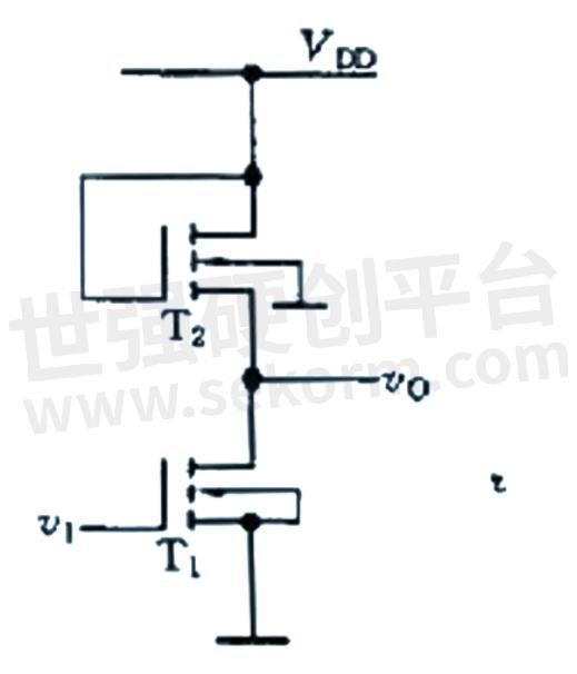
Fig.3
Its output voltage is close to 0 or VDD. When processing high-frequency signals, the inverter generally has several important indicators. If the inverter is not fast enough in transition, it will lead to distortion when processing high-frequency signals.
Overall, when only one MOS transistor is used, a pull-up resistor is required, but this can result in a larger structure and higher static power consumption. When N MOS and P MOS are paired on the same substrate, C MOS specifies that P MOS is pulled up and N MOS is pulled down. When the inverter works statically, it can always output high-quality high and low levels without relying on pull-up and pull-down resistors, and achieves very low static power consumption!
Lingxun Microelectronics is a national high-tech enterprise that focuses on the research and development, packaging testing, and sales of power semiconductor devices. It is committed to becoming an outstanding manufacturer of power semiconductor devices, assisting in the localization of core power semiconductor devices, and providing customers with high-quality and reliable power device products and comprehensive technical support. It currently has a main product line including Schottky, LowVF Schottky, fast recovery, high-voltage MOS, medium and low voltage MOS, super junction MOS, IGBT single transistor, and SiC (silicon carbide) diode. The products are widely used in various fields such as power adapters, LED lighting, brushless motors, lithium battery management, and inverters.
- +1 Like
- Add to Favorites
Recommend
This document is provided by Sekorm Platform for VIP exclusive service. The copyright is owned by Sekorm. Without authorization, any medias, websites or individual are not allowed to reprint. When authorizing the reprint, the link of www.sekorm.com must be indicated.


