The RF Engineer‘s Essential Guide to Frequency Counters
Frequency Counters must be an essential instrument on every RF engineer and precision electronic engineer's desk. In this article, learn:
The necessity of a frequency counter
The different types of counters
The industries that use them
Their construction and working principle
Tips to select and use them effectively
What Is a Frequency Counter?
A frequency counter accurately measures the frequencies of signals whose waveforms are sinusoidal, square, triangle, sawtooth, or other regular, repetitive patterns.
These instruments can measure frequencies and timing characteristics of both analog and digital signals.
Do You Need Frequency Counters? Frequency Counters vs. Oscilloscopes and Other Devices
Other instruments like oscilloscopes, spectrum analyzers, and frequency meters (like old analog-style needle gauges) can also measure frequency.
However, what sets frequency counters apart is their extremely high accuracy and precision.
While other instruments use software to measure frequency and other characteristics from digitized data, frequency counters use carefully engineered hardware circuits to precisely measure them directly on the input signal.
In addition, remember the following while choosing an instrument:
They offer high precision and resolution even at very high gigahertz frequencies.
They're better for continuous wave signals while software-based measurements work better for pulse signals.
You can reliably use them for long-term frequency measurements.
They are simpler and faster to use compared to oscilloscopes or spectrum analyzers.
What Are the Different Types of Frequency Counters?
Frequency counters come with a wide variety of capabilities and form factors. We first look at the different types based on capabilities.
Types of Frequency Counters by Capability
The primary method of categorization is based on their target industries and capabilities.
Instead of pure frequency counters, many customers prefer all-in-one universal counters that support common ancillary measurement capabilities, like signal timing, along with frequency measurement. They can typically measure:
Frequency: This is the number of full cycles completed in unit time.
Period: This is the time interval of a full cycle of the signal.
Frequency ratio: It measures the frequency ratio of two input signals.
Time interval: This measures the time delay between events of two input signals.
Time interval error: This measures the variation in timing relative to an expected or ideal value.
Pulse width: This measures the time taken by a pulse, typically the high of a digital signal.
Rise and fall times: These are the times taken by a digital signal to go from low to high states and back.
Phase angle: This measures the phase difference between two input signals.
Duty cycle: This is the percentage of a full cycle for which the signal, typically a square wave, is high.
Voltages: The maximum, minimum, and peak-to-peak voltages of a signal are reported.
Signal power: Some universal counters include built-in power meters to report the signal power.
In addition, these instruments support higher-level statistical and analytical functions like:
Histogram plots to view the distribution of frequency measurements and detect stability or noise issues
Trend plots of frequencies to detect drift and similar problems
Statistics of frequency measurements to detect jitter
Totalized metrics of frequency readings
Allan deviation, a measure of frequency stability
Radio frequency (RF) counters, or microwave frequency counters, are heavily used in RF engineering. Their measurable frequencies range from a few kilohertz (kHz) to hundreds of megahertz (MHz) and even tens of gigahertz (GHz). For example, the Keysight 53230Auniversal counter/timer base model supports up to 350 MHz while an advanced model supports up to 15 GHz.
RF counters are built differently because digital circuit elements like flip-flops are too slow to keep up with the high-speed transitions of GHz-range radio signals. So RF counters use prescalers or other frequency downscaling components to first reduce the frequencies of input signals to the MHz range.
3. Counter Timers
These are also called time interval analyzers and are optimized for precise time interval measurements.
These counters are specialized for analyzing modulated signals where the carrier signal is periodic but that pattern's obfuscated by a frequency modulation scheme.
Types of Frequency Counters Based on Form Factors
Frequency counters can also be classified based on their form factors and interfaces into:
Benchtop instruments
Handheld instruments
Hardware modules that plug into modular test equipment
Embedded blocks in application-specific integrated circuits
Logic blocks in field-programmable gate arrays
Which Industries Use Frequency Counters?

The different types of frequency counters are used wherever very precise frequency and timing measurements are required, like the industries below.
Electronic Component Manufacturing
Precise frequency and timing measurement are essential for the quality control of a variety of electronic components like:
Oscillators
Phase-locked loops
Clock modules
Analog to digital converters
Timer circuits
Frequency dividers
Frequency counters are used as testers in these industries.
Defense
RF counters are used for the quality control of critical radar and sonar systems.
Global Navigation Satellite Systems (GNSS)
GNSS constellations like the Global Positioning System heavily rely on precision in timing and frequency characteristics.
Telecommunication Systems
Similarly, frequency counters are used to achieve precise timing and frequency characteristics in wireless telecommunication equipment like 5G base stations.
How Does a Frequency Counter Measure Frequency?
Frequency measures the number of complete cycles of a signal in unit time. There are two frequency measurement approaches.
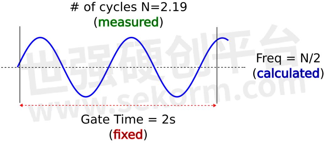
The first, called the direct frequency measurement technique, just counts the number of cycles completed in a fixed time interval called the gate time. This works as follows:
A very precise clock called a timebase does the gating, which is the process of measuring the number of cycles completed during a fixed gate time interval.
It reports the frequency as the number of cycles measured divided by the gate time.
Some disadvantages are obvious here:
The gate time need not coincide with the signal's cycle, leading to inaccurate measurement of the number of cycles.
For low-frequency signals, each cycle may take a long time. The counter has to set a long gate time to measure the cycles accurately.
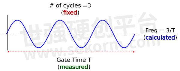
An alternative and better approach is the reciprocal measurement technique. Instead of counting the number of cycles completed in a fixed gate time:
It waits for a fixed (internally configured) number of cycles to complete.
It precisely measures the time taken for these many cycles to complete, using a high-precision internal or external timebase. That time is its gate time.
It calculates frequency by dividing the number of cycles by the measured gate time; hence the name reciprocal because it's measuring the time per cycle and then taking its inverse to calculate frequency.
The reciprocal technique's advantages include:
The same number of digits of frequency resolution regardless of the input frequency, be it hertz or gigahertz
Very accurate at very low and very high frequencies
However, reciprocal frequency counters are more expensive to build.
What Are the Key Components of a Frequency Counter?

The precision of frequency counters is because of the components that constitute them as explained in the sections below.
1. Precision Timebase
The timebase is an internal clock and gating circuit used for precise measurement of cycles or timing based on the measurement technique.
It's typically one of the following crystal oscillator circuits:
Room temperature crystal oscillator: It uses a simple quartz crystal that maintains a fairly stable frequency at typical room temperatures and is suitable for non-critical uses.
Temperature-compensated crystal oscillator: It's able to maintain stable frequencies by compensating for temperature fluctuations due to operating conditions or environmental changes.
Oven-controlled crystal oscillator (OCXO): Also called a high-stability oven timebase, the oscillator is housed in a mini-oven that maintains a constant temperature to achieve extremely high stability and accuracy.
Timebases are prone to timebase errors from aging and temperature effects. To maintain the highest stability and accuracy over time, ensure meticulous maintenance and regular calibration.
2. Input Amplifier, Attenuator, and Prescaler
These components modify the input signal to match the counter's circuitry. They boost weak signals, reduce strong signals, block high-frequency noise, and provide impedance matching.
RF counters must ensure that the high input signal frequencies are downscaled so that the digital circuits downstream can keep up with their transitions. So they use high-speed prescalers, transfer oscillators, or heterodyne converters.
3. Trigger or Comparator Circuit
The trigger circuit determines exactly when each cycle of the input wave starts and ends.
4. Counter Circuit
This is where the actual counting of cycles and measurement of time occurs. It consists of digital logic circuits with components like flip-flops and NAND gates that are actuated by the input signal whenever it crosses the trigger levels.
5. Microprocessor
A microprocessor:
Controls the frequency counter's operations
Stores and transfers data
Performs statistical and other analyses
Communicates with users or other devices
6. Power Supply
A frequency counter uses a high-quality power supply with very low ripple and noise.
7. Interface Circuit and External Interfaces to Other Equipment
Most modern frequency counters can interface with personal computers and automated test equipment through the following input/output interfaces:
General Purpose Interface Bus (GPIB): This is a hardware and data exchange standard for attaching programmable instruments to a computer. It includes the Standard Commands for Programmable Instrumentation (SCPI) standard that specifies a set of commands and semantics for each instrument class.
Universal serial bus (USB): Frequency counters can transfer the measured data to USB storage devices.
RS-232: This serial bus can be used to transfer data to a computer in custom binary formats.
LAN extensions for instruments (LXI-C): This is an SCPI over ethernet protocol that enables browser-based control of instruments.
8. Display Circuit
If the frequency counter is a standalone instrument, it's typically equipped with a liquid crystal display (LCD) and a display circuit to show measurements, analysis results, and graphical outputs like histograms.
What Are the Key Specifications of Frequency Counters?
Review these key specifications when you choose a frequency counter:
Number of input channels
Frequency range and maximum frequency of each channel
Frequency resolution, which is the precision of the frequency expressed as the number of digits
Time resolution, which is the smallest measurable time difference between two events in a single shot and expressed in nanoseconds or picoseconds
Phase resolution in degrees
Timebase error, timebase aging coefficient in parts per year or parts per million, and the timebase uncertainty
Data transfer rate to external interfaces
Tips for Achieving High Accuracy and Precision
Follow our tips for accurate measurements usingfrequency counters:
1 Avoid automatic arming mode because it's the least accurate. Both the time resolution and the systematic uncertainty, which contribute to the overall measurement error, can be improved by using one of the other arming modes — external, time, or digit.
2 Keep the timebase warm by always having it powered up. This gives an order of magnitude improvement in the annual aging rate compared to regularly powering down.
3 Use the best available timebase. A high-stability oven timebase doesn't require frequent calibration, but it's recommended for less stable ones.
4 Pay attention to trigger levels and trigger level timing errors, especially when the signal is noisy.
5 Lock all timebases to a single clock to avoid jitter due to independent timebases.
6 Set the trigger level so that it intersects the signal at the point of maximum slew rate to minimize the amount of time taken for the trigger condition.
7 Don't set the trigger band so narrowly that any noise gets counted as zero crossings.
We implement all these measures in our frequency counters products described next.
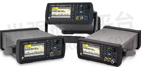
Keysight Frequency Counters

Keysight's 53200 Series RF and universalfrequency counters offer the following state-of-the-art features:
One to three input channels
High-quality temperature-compensated timebases with just one part per million annual aging
Optional high-stability oven timebases with as low as 50 parts per billion annual aging
Extremely high, 12 digits frequency resolution
Single-shot time resolution as low as 20 picoseconds
Built-in advanced data analysis and graphing capabilities
Learn more through Frequency Counter page or datasheets of our three models for very detailed specifications and accuracy calculations:
53230A 350MHz universal frequency counter
53220A 350MHz universal frequency counter
53210A 350MHz RF counter
Achieve Unbeatable Accuracy With Keysight Frequency Counters
In this guide, you got an overview of the internals and applications of frequency counters.
- +1 Like
- Add to Favorites
Recommend
This document is provided by Sekorm Platform for VIP exclusive service. The copyright is owned by Sekorm. Without authorization, any medias, websites or individual are not allowed to reprint. When authorizing the reprint, the link of www.sekorm.com must be indicated.
Integrated Circuits


Discrete Components


Connectors & Structural Components


Assembly UnitModules & Accessories


Power Supplies & Power Modules


Electronic Materials


Instrumentation & Test Kit


Electrical Tools & Materials


Mechatronics


Processing & Customization


