Optical Power Meters: Understand Their Uses and Internals
Modern high-speed networks run on optical fiber because of its incredible speed and virtually unlimited capacity. Optical Power Meters are a key element in the optimization and maintenance of such optical networks and of their components.
In this article, learn:
· What optical power meters do
· Who uses them and how
· How they work
What is an optical power meter?
An optical power meter (OPM) measures the power levels of light signals in devices that transmit data or power using light.
The term "optical power meter" may sound generic, but in popular usage, it specifically implies a fiber optic power meter. For light power measurements outside the field of fiber optics, alternative terms like light meter, laser power meter, and photometer are more common.
OPMs typically report the power either on a watts scale covering picowatts to milliwatts, or in decibel-milliwatts (dBm), which is the logarithmic ratio of the measured power to the reference value of one milliwatt. An increase in reading by one dB.
OPMs are often combined with other test instruments. Let's look at how different industries use them in more detail.
Which industries rely on optical power meters?

Any industry that uses optical fibers for communication requires OPMs. Let's look at some of them.
Telecommunications
Modern telecommunication core networks, both wired and wireless, are optical fiber networks because of their superb speed and capacity. Even the undersea cables connecting continents are part of the optical network.
In many markets, even the last-mile broadband access networks use technologies like fiber-to-the-home (FTTH) and fiber-to-the-X (FTTX) for high-speed internet. Fiber is even replacing ethernet inside our homes and offices around the world.
All these fiber networks use optical power meters and related instruments for their testing. For example, last-mile passive optical networks (PONs) are tested using special handheld optical power meters called PON power meters.
Data centers and cloud computing
Modern data centers and cloud computing services require 400G, 800G, and even 1.6T ethernet to keep up with the bandwidth demands of their exponentially growing customer base.
Such high-speed connections are needed for a variety of connections, from backplane interconnects to the connections between processors and accelerators like graphical processing units (GPUs) and field-programmable gate arrays (FPGAs). These accelerators are used for a variety of modern tasks like artificial intelligence inference and high-frequency trading.
To achieve these extreme speeds, companies use high-precision technologies like:
· Silicon photonics, which are techniques to implement miniaturized optical assemblies directly on silicon chips for very low latencies and high energy efficiencies
· Advanced modulation techniques like pulse amplitude modulation (PAM4) for very low bit error rates
· Coherent transmission techniques and their advanced modulation schemes
Additionally, engineers must ensure that all these techniques conform to tight power loss budgets and signal-to-noise tolerances using high-precision test and measurement devices like optical power meters, tunable laser sources, polarization synthesizers, and optical time domain reflectometers.
Avionics and Defense
Avionics and defense systems rely on optical fiber for speed and bandwidth. The high level of reliability and redundancy in these systems requires heavy use of OPMs for testing and maintenance.
You typically combine OPMs with other fiber optic test instruments, but they are sometimes used independently as well. We review both types of applications below.
Optical Power Measurement
You can use an OPM independently to measure the power level of a fiber optic signal. It essentially measures the instantaneous total energy of all the photons coming out of a fiber optic cable.
Optical power meters can measure the power of both single-mode and multimode fibers. In single-mode fiber, the rays travel down its entire length without any internal reflection at all. In multimode fiber, multiple rays enter at different angles and possibly have different wavelengths as well.
[Describe the difference between averaging and peak power meters here (Keysight offers only averaging optical power meters)]
For the characterization of fiber optic components, an OPM is combined with a light source, typically a laser with a wavelength equivalent to the use case of the component under test.
A typical OPM setup consists of the following two components.
1. Optical Laser Source (OLS)
A light source is an instrument that emits light signals with different characteristics like wavelengths, power levels, or timings. The light is emitted by light-emitting diodes (LEDs) or lasers. A light source can be of many types depending on the characteristics of its light emissions and testing purpose:
· Single-mode or multimode
· Polarized or non-polarized
· Broadband sources like LEDs or narrowband sources like lasers
· Tunable lasers (a type of laser whose wavelength can be changed electrically)
· Wavelength-centered signals
2. Optical Power Meter
This is the main device that:
· Measures the power level, preferably at high rates for improved measurement througput
· Records them internally
· Transmits the data to software running on a computer over an ethernet, USB, or General Purpose Interface Bus (GPIB) connection.
OPMs come in various form factors. The optical sensor is either part of an internal detector circuit or housed in an external optical head for flexible positioning.
Bench-top and handheld optical power meters have LCD screens to display average and instantaneous power values.
However, OPMs may also be displayless, or modular platforms meant for high-throughout measurements of multiple fibers or multiple ports. They just collect and stream the data from all channels to an attached computer.
Optical Loss Test Set
An optical loss test set (OLTS) compares power levels with and without a fiber link to determine the link's net power loss. The fiber link may be a simple fiber or an assembly of fibers, splices, fusion splicers, connectors, attenuators, and other optical devices.
To test its net loss, connect a suitable OLS to one end of the link and the power meter to the other end. Set the meter to the same wavelength as the OLS and measure the power.
Then remove the fiber link, connect the OLS directly to the meter, and measure the power again.
The difference between these readings is the net power loss of that fiber link. These losses include:
· Insertion loss
· Return loss
· Polarization-dependent loss
Optical Time Domain Reflectometer (OTDR)
An OTDR is an advanced fiber optic tester that can measure optical loss between any two points in a fiber or optical assembly. You can use it to detect fiber breakages, loose connections, faulty or dirty connectors or couplers, and other problems as shown in this OTDR trace of power in decibels (dB) against distance.
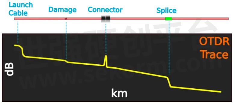
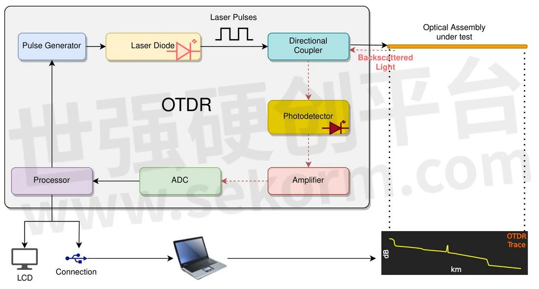
An OTDR contains an optical power meter as an internal component for testing power between two points. A typical OTDR schematic is shown below.
For simple everyday testing of cables, OTDR is often used along with a Visual Fault Locator (VFL). The OTDR measures the distance to problem points while the VFL enables visual checking and verification.

What Are the Key Components of an Optical Power Meter?
Let's look at what's inside an OPM.
Sensor
The sensor is the most critical component. It converts the incident light energy into an electrical signal. Different types of sensors are available depending on their working principles as described below.
Photodiode Sensors
Photodiode sensors convert light energy to electrical energy. Three common types include:
1. Silicon (Si): Si sensors can detect very low power levels (nanowatts to tens of milliwatts), but their wavelength range is restricted to around 1,100 nanometers (nm).
2. Germanium (Ge): Ge sensors are good at higher power levels (hundreds of milliwatts). However, they don't work well at low power levels and have low accuracy over the entire wavelength range.
3. Indium Gallium Arsenide (InGaAs): InGaAs sensors work great at intermediate power levels and higher wavelengths.
Thermopile Sensors
Thermopile sensors absorb light and heat up to generate a temperature difference between two thermocouple surfaces. This temperature difference between two dissimilar metals generates a proportional voltage.
Pyroelectric Sensors
In pyroelectric sensors, absorbed light leads to a temperature change and generates an electrical signal.
Detectors or Optical Heads
A detector houses the sensor and its related filtering and processing circuitry. It's typically an internal component of the OPM.
In contrast, an optical head is a detector available as a separate external attachment for flexible positioning. You can easily detach an optical head and replace it with another better suited to the light source or fiber being tested.
Typical bench-top and handheld optical power meters support one or two detectors or optical heads. High-end multi-port meters support up to eight or more detectors or optical heads. Some rack-mounted meters support hundreds of ports.
Sensor Amplifier
A sensor amplifier circuit boosts the electrical signal from the sensor for reliable detection and measurement. Since sensor response is very sensitive to the input signal's wavelength, the amplifier should be carefully calibrated to boost the signal to a level based on the wavelength.
Connector Interfaces
A wide variety of connectors are used in photonics:
· For single-mode fibers, there are ST, SC, LC, FC, and more.
· For multimode fibers, there are multi-fiber push-on (MPO) connectors and their variants. MPO-terminated cables are widely used in high-density environments like data centers.
Optical power meters support most of these connectors through the use of connector adapters.
Other Optical Elements
An optical power meter may contain elements like:
· Lenses: They focus the light on the sensor.
· Filters: They prevent unwanted wavelengths from affecting the measurements.
· Attenuators: They reduce the light signal's power to protect the sensor from damage.
How does an optical power meter work?
The typical operation of an optical power meter is as follows:
· Set the wavelength: The meter is set to the known wavelength of the input signal so that its circuit and software are correctly calibrated to that wavelength.
· Filtering and attenuation: The input light is filtered and attenuated inside the detector or optical head to prevent unwanted wavelengths and damage to the sensor.
· Sensor activation: The sensor generates a signal that's proportional to the light signal's energy.
· Amplification: The sensor's signal is amplified suitably based on the wavelength.
· Analog to digital conversion: The meter's analog signal is converted to a digital value for display and recording purposes.
· Display: If the meter has a display, the power reading is shown.
· Storage: The digitized value is stored in internal memory and storage.
· Data export: The values are transmitted to an attached computer over USB, ethernet, or GPIB.
Optical power meter specifications

Let's look at some of the common parameters you'll find in an OPM datasheet.
Power Range
A typical OPM is calibrated to be linear in the 10 dBm (10 milliwatt) to -50 dBm (10 nanowatt) range. In this range, a change in the actual power results in a linearly proportional change in the measured power.
High-sensitivity meters may range from as low as -110 dBm to as high as +30 dBm but typically only for single-mode fiber testing.
Why high dynamic range is important
Dynamic range is the ratio of the highest power to the lowest power. A high dynamic range enables many applications. For example, if there is a problem like a connector fault or a break in the cable, it can cause the optical power to drop very low. An OTDR with a high-dynamic range OPM can detect and troubleshoot these problems.
Wavelength Range
OPMs are optimized for the special wavelengths that are popular in fiber optic systems:
· 850 nm for short-distance applications, such as local area networks
· 1,300-1,310 nm for medium-distance applications, such as in data centers. This wavelength range benefits from the fiber’s low chromatic dispersion (CD) which enables high data rates without CD compensation
· 1,550 nm for long-distance applications like undersea cable, because this is where the optical fiber’s attenuation is minimal
· 1,625 nm for monitoring signals and for additional bandwidth provisioning
Closely related are the sensor's and meter's spectral responsivity curve, which shows the responsivity of the sensor at each wavelength. Responsivity is the ratio of the generated current or voltage at the sensor per watt of incident optical power. The spectral responsivity curve tells you the wavelength range where the sensor and meter show linearity, i.e., their reading is linearly proportional to the actual input energy.
A set of example spectral responsivity curves is shown below for Keysight's optical power meter head products.
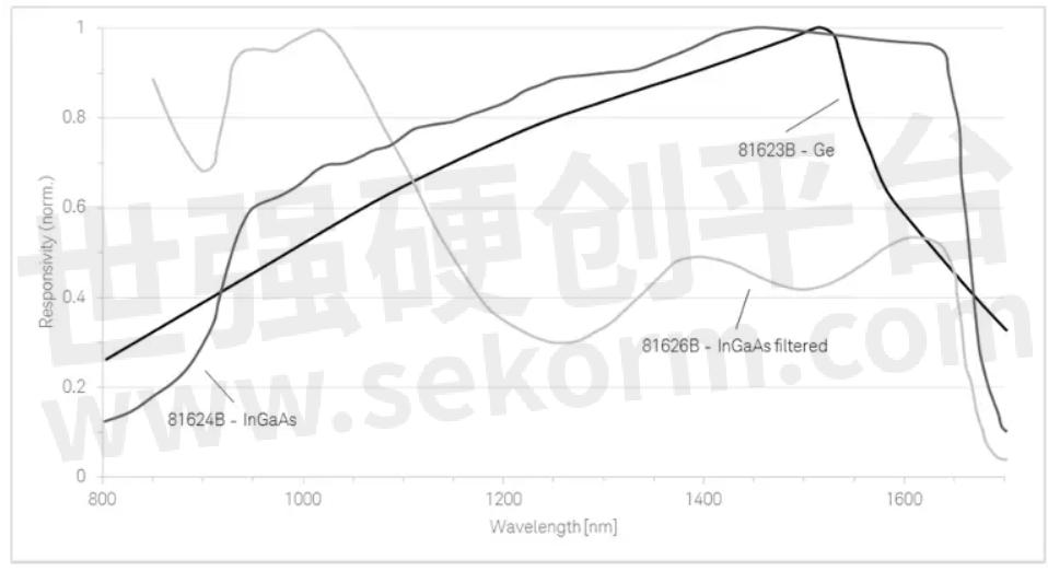
In this example, the 81623B is exceptionally linear in the 800-1,500 nm wavelength range.
How Accurate Are Optical Power Meters?
Uncertainty in sensor accuracy can be as high as 2.5%-4%.
Additionally, the total uncertainty is determined by other factors, including sensor uniformity, active area of the sensor, linearity, and temperature. Accounting for them, uncertainty can go as high as 5%-6%.
Careful calibration can help keep the meter's total uncertainty in the 2.5%-4.5% range.
Keysight Optical Power Measurement Products
At Keysight, we offer you a wide range of standalone as well as modular optical power meters and related test equipment for optical applications. Let's look at some of our key products.
Standalone Optical Power Meters
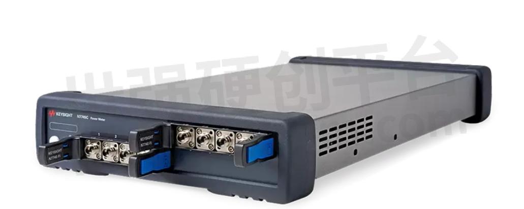
Our N774xC family of standaloneoptical power meters include:
· Multiport meters like the N7745C with up to eight channels, high dynamic range, and low uncertainty for long-distance wavelength applications
· High-sensitivity meters like N7748C with a very high dynamic range of -110 dBm to +10 dBm and low uncertainty of ±2.5%
Optical Power Meter Heads
The 8162xCand 8162xB families offer a variety of optical heads for flexible positioning and interchangeable connectivity with the N774xC meters.
Lightwave Modular Platform
The Lightwave Solution Platform offers expandable optical mainframes like the 8164B that accept specialized modules like sensors and loss detectors.
Our power sensormodules are designed for use with the Lightwave modular system.
The N7753C return loss meter is a standalone instrument with two power meter sensors to measure return loss.
Upgrade your optical systems with keysight technology
In this guide, you got an overview of optical power meters and their internals. Today's fastest petabyte-scale data networks wouldn't be possible without optical fibers. Photonics is revolutionizing other sectors as well, from avionics to health care, from quantum photonics to AI/ML.
Whatever industry you're in, Keysight is your reliable test and measurement vendor. We also provide expert-level, accredited calibration services for your optical power meters of any brand.
- +1 Like
- Add to Favorites
Recommend
- Keysight Technologies Acquires Quantum Benchmar, Augmenting Keysight‘s Quantum Portfolio
- Keysight First to Gain GCF Approval of Cases for Validating 5G New Radio mmWave Devices in Standalone Mode
- Keysight‘s O-RAN Test Solutions Enable Xilinx to Accelerate Development of Massive MIMO Radio Reference Design
- Keysight and Transphorm Create Power Supply Reference Design that Lowers Product Costs; Speeds Time to Market
- Keysight Massively Parallel Board Test System Selected by LACROIX in Automotive Printed Circuit Board Manufacturing
- Keysight, TIM and JMA Wireless Join Forces to Showcase O-RAN Technology at Mobile World Congress 2021
- Keysight First to Gain OmniAir Qualified Test Equipment Status, Accelerating C-V2X Device Certification
- Keysight Delivers New Solution for Benchmarking 5G End-user Quality of Experience in Indoor Environments
This document is provided by Sekorm Platform for VIP exclusive service. The copyright is owned by Sekorm. Without authorization, any medias, websites or individual are not allowed to reprint. When authorizing the reprint, the link of www.sekorm.com must be indicated.
Integrated Circuits


Discrete Components


Connectors & Structural Components


Assembly UnitModules & Accessories


Power Supplies & Power Modules


Electronic Materials


Instrumentation & Test Kit


Electrical Tools & Materials


Mechatronics


Processing & Customization


