SCME is Devoted to Providing the Best Protection and Power Control Solutions for Gas Igniter

Gas Igniter
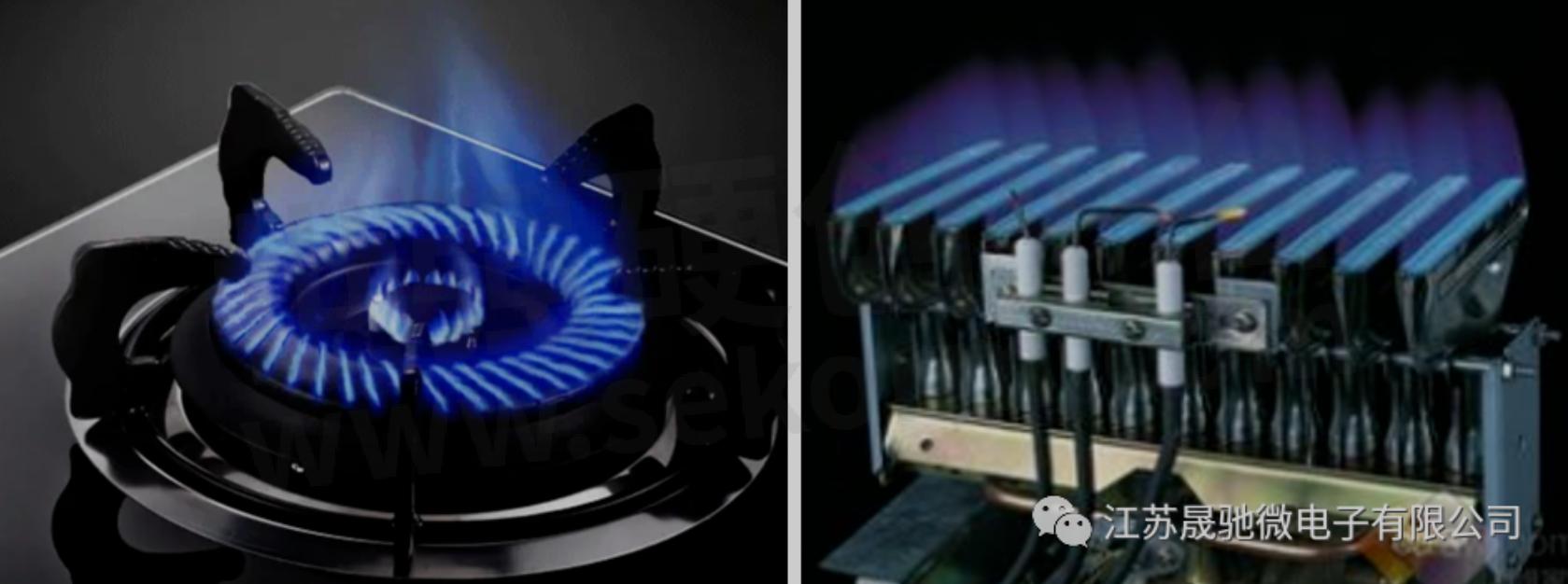
The gas igniter is an electrical unit that generates a high-voltage spark. It is an important part of consumer gas appliances and industrial gas-firing applications.
Application area
1). Gas cooking appliances
2). Gas water heater
3). Gas oven/furnace
The Challenge
Cooking appliances and water heaters are common products for home supplies. Low cost and high reliability are becoming more and more important to win the market share.
As a domestic company in circuit protection and power control, SCME has always devoted itself to providing the best protection and power control solutions to help achieve lower cost and more reliable products.
Existing gas igniters are categorized as below several conditions:

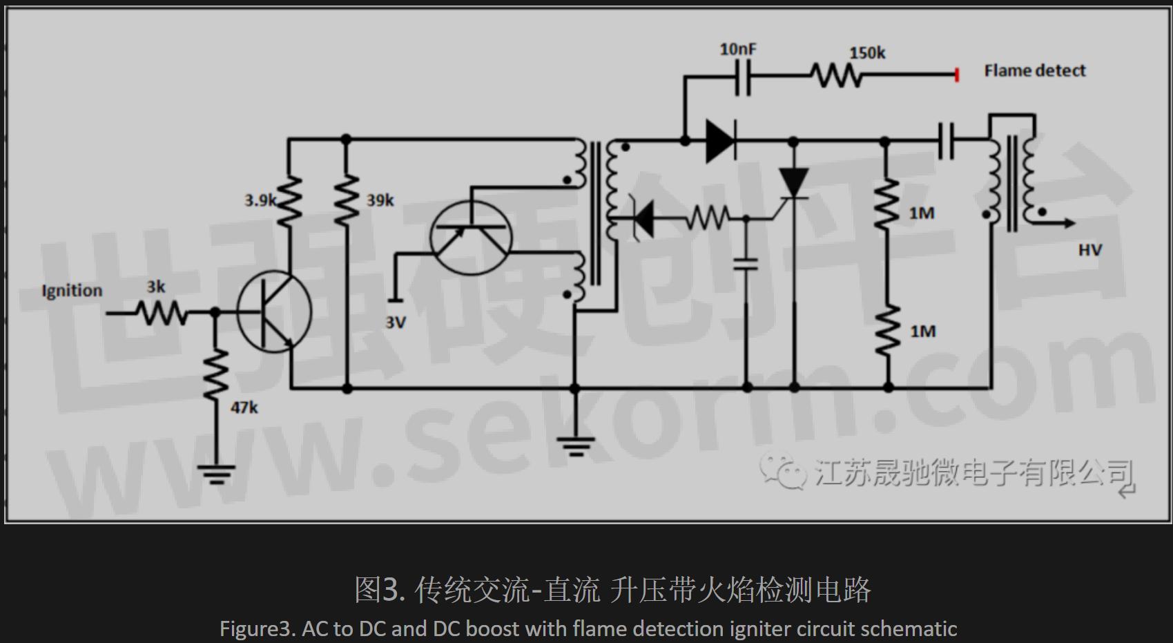
Traditional DC boost gas igniter circuit without flame detection uses a combination of SCR and Zener diode, coupled with capacitors, and resistors to produce high voltage pulses. The shortcoming of this solution is circuit complexity and large board space, shown as a blue area in the following schematic. Also, the yield at the igniter manufacturing side is impacted by these variations.

To improve design cycle and igniter reliability, SCME developed a series of asymmetric SIDAC products (highlighted in green) to replace components in the aforementioned schematic This dramatically cuts component count (5pcs to 1pc) and improves with better yield, productivity, and reliability.
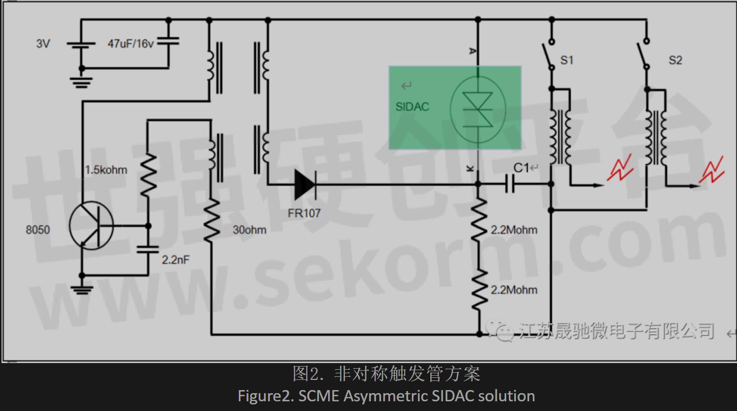
The benefit of this proposed schematic is low cost, high reliability, and high productivity. SCME offers both axial lead and surface mount packages of SIDAC to accommodate different assembly methods. Both traditional and new schematics generate repetitive high voltage pulses at approximate 80ms intervals, with identical voltage values.
The SIDAC is a 2-terminal silicon uni-lateral voltage-triggered switch. Once the voltage across terminals exceeds SIDAC breakover voltage (VBO), SIDAC instantly switches from a very high impedance state (off-state) through a negative resistance region to a very low impedance state (on-state), passing a very high current pulse through SIDAC. SIDAC stays on-state until the current drops below the minimum holding current of SIDAC.
In this igniter schematic, C1 is a charging and discharging capacitor.
When S1 or S2 is closed (pressed on), current from the 3V battery through the primary coil of the high-voltage-pulse-generating transformer activates Transistor 8050, discharging the 3V battery through the primary coil of the top side of a step-up transformer.
High voltage on the secondary coil charges C1 through the diode, as well as generates a negative voltage in the bottom side of the primary coil to interrupt the base current to transistor 8050, then deactivates 8050 and stops battery discharge. Once battery discharge stops, the voltage on secondary coils disappears. As soon as the negative voltage on the secondary coil disappears, the current from the 3V battery again activates 8050. This cycle continues until the C1 voltage reaches SIDAC VBO.
Once the C1 voltage exceeds SIDAC VBO, SIDAC instantly turns on to on-state, discharging C1 through the primary coil of the high-voltage-pulse-generating transformer, generating a high voltage pulse on the secondary side. When stored energy in C1 is drained, SIDAC turns off to off-state, restoring current from the 3V battery to transistor 8050, and charging to C1 starts again. This cycle of operation continues as long as S1 or S2 is closed, and keeps generating high voltage pulse.
For the AC to DC power supply igniter, because it needs 4kV EFT compliance, the SIDAC VBO needs to be considered. Below Figure 4 is an Asymmetric SIDAC solution to meet the 4kV EFT test with VBO from 200V to 215V.

For some flame detection combined with an HV needle igniter circuit such as in figure 5. Asymmetric SIDAC reverse voltage needs to be considered too because of the flame oscillation signal.
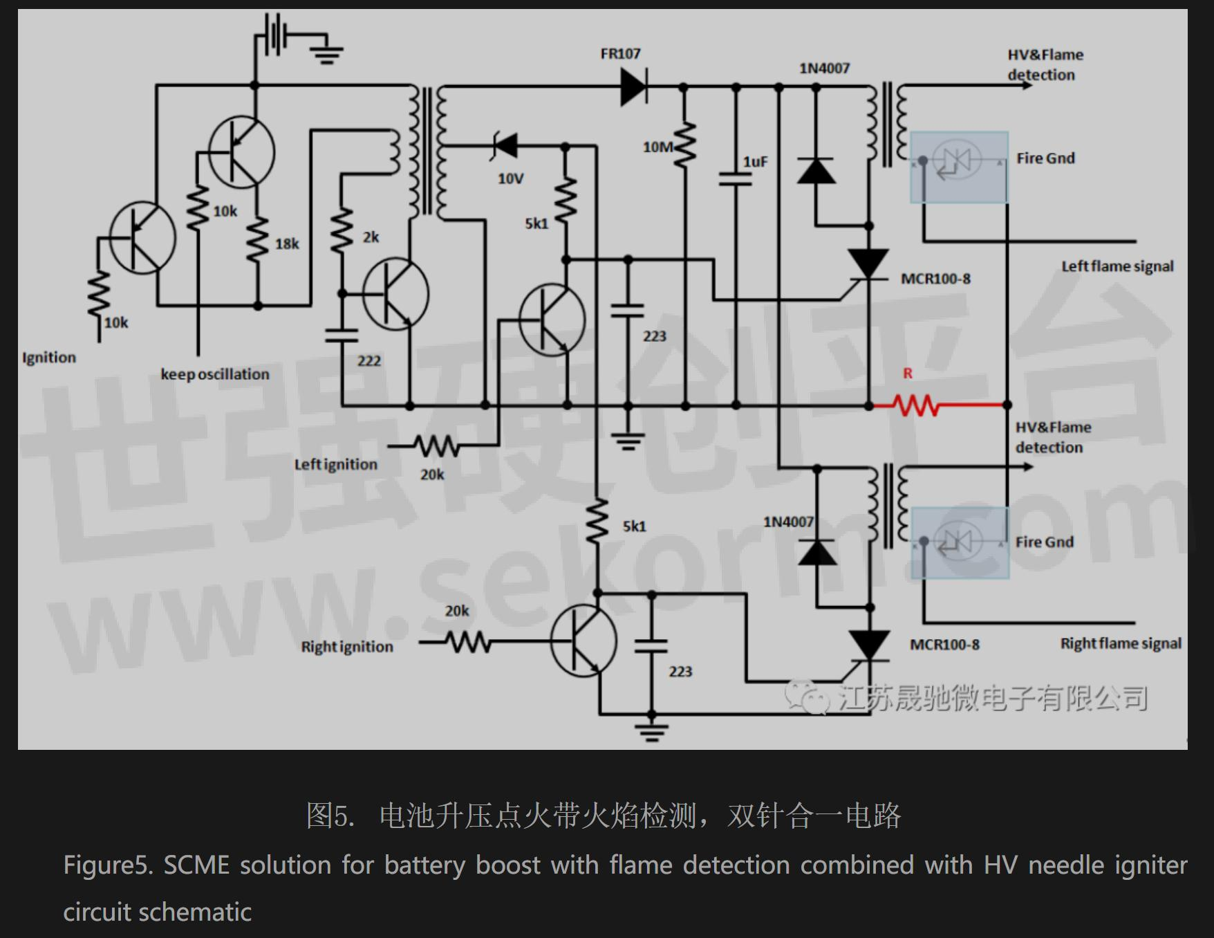
As figure 5 shows, this circuit is for a flame detection needle combined with an HV fire needle. It uses SIDAC to isolate flame detection signal, so it needs the reverse side of SIDAC certain voltage to block the negative oscillation signal. A minimum 45V voltage is required to accomplish such flame detection. For SIDACside voltage, typically from 142V to 210V.
Another need mentioned is the resistance R between fire ground to power ground, the value could be varied from 1k to 51k depending on the fire detection oscillation amplitude. Lower fire oscillation amplitude, lower the resistance; higher fire oscillation amplitude, higher the resistance.
For that AC power direct drive igniter below figure6 showed, because of higher trigger frequency up to 100Hz, higher ITRM SIDAC is suggested for such an application.

SCME SIDACs feature glass-passivated silicon die and solder-attach assembly to ensure a rugged and dependable device capable of withstanding harsh environments and infinite operation life.

For special trigger voltage requirements of the SIDAC, please contact factory for more information.

- +1 Like
- Add to Favorites
Recommend
This document is provided by Sekorm Platform for VIP exclusive service. The copyright is owned by Sekorm. Without authorization, any medias, websites or individual are not allowed to reprint. When authorizing the reprint, the link of www.sekorm.com must be indicated.
Integrated Circuits


Discrete Components


Connectors & Structural Components


Assembly UnitModules & Accessories


Power Supplies & Power Modules


Electronic Materials


Instrumentation & Test Kit


Electrical Tools & Materials


Mechatronics


Processing & Customization


