Easy-to-install Benewake Intelligent Traffic System Solution with High Accuracy and Low Cost

The technology behind traffic light timing programs is rapidly evolving. The aim is to further develop adaptive signal control technology (ASCT) in an effort to adapt traffic light timing programs to the demands of real-time traffic and thus reduce traffic congestion in urban areas.
ITS provide real-time information for decision-making algorithms that can be then used by travelers and traffic management systems. Different advanced driver assistance systems (ADAS) have been developed to make drivers aware of their surroundings while driving. Some of the most common include forward collision warning (FCW), which detects a leading vehicle and calculates relative speed and distance in order to generate warning signals based on time to collision (TTC); traffic sign recognition (TSR) or systems that recognize different traffic signs to augment the field of view of the driver; traffic light recognition (TLR), to detect and recognize traffic lights; and traffic light assistance (TLA) systems that acquire data related to the signal timing, tailback, and geometry of intersections and combine it with in-vehicle data. For each of them, collection of different data is required, such as speed or distance to the following car or next traffic light.

Rigidity analysis
With the rise of smart cities, the intelligent transportation industry has become the most promising industry with the most policy inclination in the current subdivision.
According to the actual application, in order to meet the needs of the scene, the program needs to realize the detection of multiple parameters, such as vehicle model (contour), number of axles, vehicle length, license plate number and other parameters. The rigidity analysis of each parameter is as follows:
Table 1 Rigidity analysis of vehicle classification applications
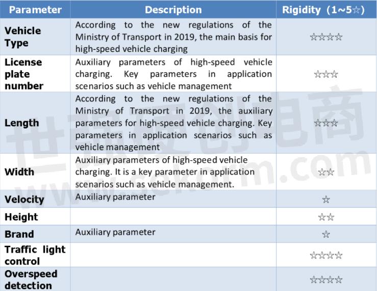
The above is based on the survey of existing customers, the rigidity of different customer needs is different.
Existing solution introduction
![]() Single point LiDAR
Single point LiDAR
This solution is based on the BENEWAKE single-point ToF LiDAR and consists of three parts: the data acquisition unit, using the Benewake single-point long-range LiDAR, TF03. the main control board, used to collect and process LiDAR information and control output results, control LED display screen (can be omitted); mechanical structure, used to install and fix the entire program. The scheme is as follows:
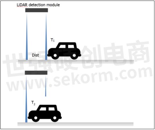
Figure 3 Benewake’s single point LiDAR solution of vehicle classification traffic statistics
Advantages analysis of solution
High frame rate
High accuracy
Long lifespan
Low cost
Easy to install
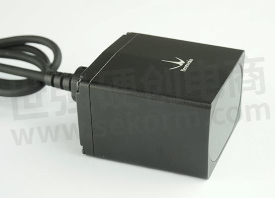
Benewake’s single point LiDAR solution: BITS
See the following conceptual diagram for details:

Figure 4 BITS LiDAR detection module
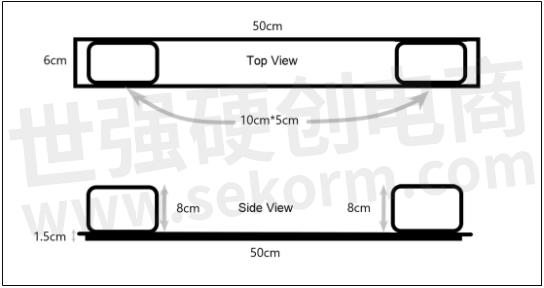
Figure 5 Dimensional drawing of BITS
The two LiDARs are installed in the vertical ground direction and the tilt-to-ground (40 °) direction respectively. The tilt LiDAR and the vertical LiDAR can detect the vehicle successively, calculate the trigger time difference between the two and then calculate the driving speed of the vehicle. The data measured by the vertical radar can restore the contour information of the vehicle. The model recognition is completed by neural network algorithm.
Vehicle height information can be directly obtained by vertical radar measurement. The vehicle speed calculated by the two LiDARs, and the trigger time, calculate the available vehicle speed. The neural network algorithm is used to match and identify the original data collected by the LiDAR. The form of the original data is as follows:
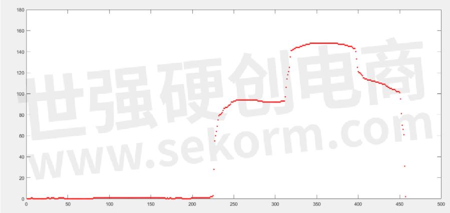
Figure 6 The original data map of the vehicle models collected by Benewake's LiDAR
After the recognition test is completed, the main control board directly transmits the test results to the customer's main control system through the data line. Transmission content includes statistics of vehicle model, vehicle height, vehicle length, vehicle speed and number of vehicle models, see data communication protocol for details.
Main function of BITS:
Traffic statistics
Overspeed detection
Vehicle speed detection
Traffic light control assistance
Installation
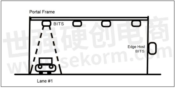
Figure 7 Installation drawing of BITS
GUI for BITS
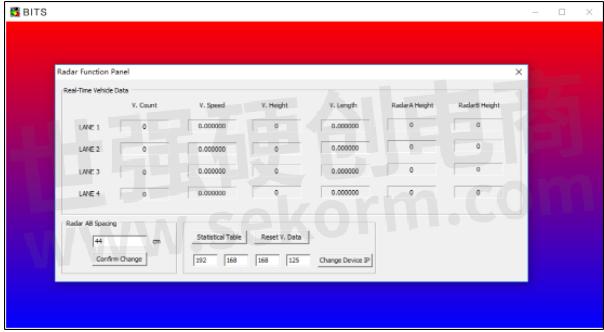
Figure 8 GUI for BITS, LiDAR monitor
Related product
TF03 180m IP67 LiDAR
- +1 Like
- Add to Favorites
Recommend
This document is provided by Sekorm Platform for VIP exclusive service. The copyright is owned by Sekorm. Without authorization, any medias, websites or individual are not allowed to reprint. When authorizing the reprint, the link of www.sekorm.com must be indicated.
Integrated Circuits


Discrete Components


Connectors & Structural Components


Assembly UnitModules & Accessories


Power Supplies & Power Modules


Electronic Materials


Instrumentation & Test Kit


Electrical Tools & Materials


Mechatronics


Processing & Customization


