What?! There Is A Capacitor in My Transformer?

EXXELIA recently designed an auxiliary transformer for a spacecraft application, where interwinding capacitance was of concern to the customer. The controller chip they were using in their power supply was noted to be “rather sensitive to excess capacitance.”
Exxelia has also supplied thousands of driver transformers for use in a subsystem of the AN/TPQ-53 Radar System in which interwinding capacitance within the toroidal windings is held to a very demanding tolerance.
But what is interwinding capacitance?
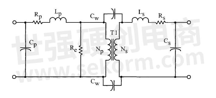
Capacitance in a transformer winding cannot be avoided. The voltage difference between turns, between winding layers and from windings to the core, creates “parasitic” capacitances in the transformer circuit. These capacitances are shown as Cp, Cs, and Cw in this schematic diagram of an electronic transformer “equivalent circuit.”

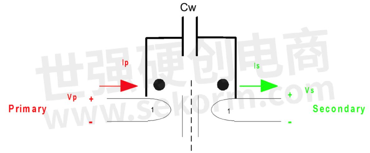
Interwinding and distributed capacitance occur in transformers due to the physical separation of, and electrostatic coupling between, different turns of wire. In general, the capacitance presents itself between the different layers within a winding and between the outside layer of one winding and the inside layer of the next.
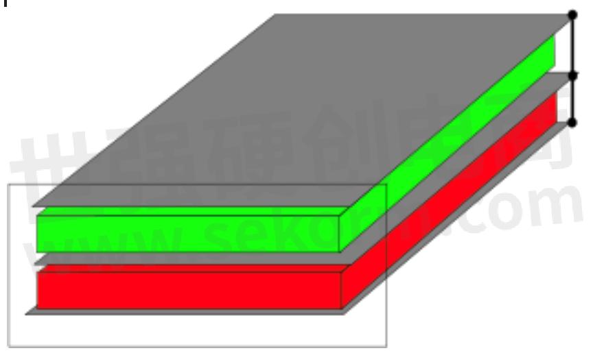
In conventional magnetics, interwinding capacitance is a function of coil configuration – the geometry of adjacent conductors and separating dielectric media. Specifically, it is directly proportional to the shared surface area of the windings (shown in green and red below), the dielectric constant of the insulator between the windings (shown in gray below), and is inversely proportional to the separation distance through the dielectric media.


In high-frequency transformer design, leakage inductance and capacitance are often competing design requirements since the beneficial parameters that provide low leakage inductance also tend to increase the interwinding capacitance.
Excessive capacitance can cause undesirable common-mode noise transmission between transformer windings or between transformer windings and core or another ground connection.
Exxelia can assist with these design challenges when creating products that have to deal with interwinding capacitance, for all types of magnetic components.
Important coil configuration design considerations must be made when capacitive coupling causes unacceptable signal transmission (for example, common-mode noise transmission or undesirable spurious ringing on a high voltage output). Windings may be configured in a way that reduces the dV/dt voltages induced across dielectric media. Conductive screen(s) tied to preferred potential(s) can also be added between adjacent windings to reduce transmission.
- +1 Like
- Add to Favorites
Recommend
This document is provided by Sekorm Platform for VIP exclusive service. The copyright is owned by Sekorm. Without authorization, any medias, websites or individual are not allowed to reprint. When authorizing the reprint, the link of www.sekorm.com must be indicated.


