Circuit Design Guidelines of Driving High Power Pulsed VCSEL Sensor

With the development of AI/IoT, smart technology, and automation technology, smart sensors have become a new market trend. Products using VCSEL as the core device of the sensor have many advantages and are widely used in ranging, proximity sensing, lidar, safety light curtain, smart home, and other fields.
Brightlaser VCSEL products can be used as sensor pulse emission light sources, with various packaging forms, SMD packaging structures, and easy integration; TO-packaging market applications are mature. Wavelengths are available in 808nm, 850nm, and 940nm. Single emitter and arrays are available to meet different power and spot shape requirements.
Advantages of Brightlaser VCSELs:
Pulsed power output: 10-15W, 25W, 50W, 100W options
Single emitter and array type selectable
Wavelengths: 808nm/850nm/940nm
Packages: Laser diode: 2016 / TO46/SMD 1x4 / SMD 1x8 / SMD 1x16
PD sensing package: 3030 (3.0x3.0mm)
Transceiver package: 3528 (3.5x2.8mm)
Application scenario:
Proximity Sensor
Range Finder
Lidar
Light Curtain
Pulsed VCSELS
In terms of supporting sensor core devices, Brightlaser products include VCSEL pulsed laser diode series, PD sensing chip series, and transceiver series. Brightlaser VCSEL sensor element with the advantages of simple pulse circuit design and easy operation.
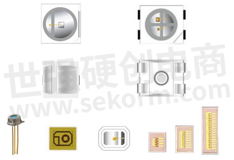
Fig.1
Pulsed VCSEL driver circuit
At the transmitting end, a MOSFET can be used to control the negative pole of the VCSEL diode to emit pulsed light (positive pole to ground).
Step 1: U2 is off, C2 capacitor left terminal is charged by HV
Step 2: U2 is turned on by control signal
Step 3: Left terminal of C2 drop to 0V while right terminal becomes -HV
Step 4: Negative pole of VCSEL becomes -HV and positive pole become 0V → pulsed laser emission occurs
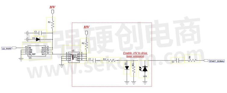
Fig.2
Transceiver
1) VCSEL laser emission – see “Pulsed VCSEL driver circuit” section for reference
2) PD sensing – PD receive laser signal → current signal → electric signal amplified
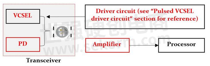
Fig.3
- +1 Like
- Add to Favorites
This document is provided by Sekorm Platform for VIP exclusive service. The copyright is owned by Sekorm. Without authorization, any medias, websites or individual are not allowed to reprint. When authorizing the reprint, the link of www.sekorm.com must be indicated.
Recommend

Application of UAV in Lidar
2021-06-25 - Application solution Article This article discusses the application of Lidar in UAVs, emphasizing its importance for real-time ranging, altitude setting, and obstacle detection in complex environments. It compares Lidar with other technologies like ultrasonic and vision-based solutions.

Based on TOF, Benewake‘s Lidar Can Be Integrated into the Robot and And Realize Obstacle Avoidance
2021-08-04 - Application solution Article Benewake’s single point solid-state lidar has independent intellectual property rights, Based on TOF, the TF series lidar can achieve fast, precise, and stable distance measurement, help the robot quickly and accurately identify the surrounding objects. They can be integrated into the robot, which can provide real-time distance information for the robot, help the robot quickly and accurately identify the objects around and realize obstacle avoidance.

High-performance Thermoelectric Coolers Offer A Flexible Active Cooling Option for Spot Cooling of Lidar Sensors
2024-10-29 - Application solution Article The lasers in Lidar systems, particularly those used in outdoor autonomous applications, require active cooling to achieve maximum resolution in high-temperature environments. As temperatures increase, the wavelength of the laser changes, resulting in increased range error. Maintaining operational temperatures within a Lidar system’s temperature limits ensures peak performance. Laird Thermal Systems High-performance thermoelectric coolers offer a flexible active cooling option for spot cooling of Lidar sensors.

Circuit design guidelines of driving high power pulsed VCSEL sensor
Supplier and Product Introduction
VCSEL SENSOR,垂直腔面发射激光器传感器,智能传感器,SMART SENSORS

TOF and LiDAR: Analysis of Core Differences
2025-11-25 - Technical Discussion TOF and LiDAR: Analysis of Core Differences in working principles, performance characteristics, and application scenarios.

The Development History of UAV-Borne Lidar
2025-11-03 - Technical Discussion The article discusses the development history of UAV-borne lidar, starting from its origins in space technology, through key milestones such as miniaturization, AI integration, localization efforts, and recent innovations in FMCW and single-photon lidar technologies, leading to broader civil and commercial applications.


11 Rumors About Lidar, Do You Know?
2021-08-10 - Technical Discussion This article discusses 11 common rumors about lidar technology, covering misconceptions about its complexity, cost, types, and applications in various environments and industries.

ROHM’s 75W High Optical Output Laser Diode for LiDAR RLD90QZW3
2021-10-07 - Product Introduction ROHM developed a 75W high optical output laser diode, RLD90QZW3, for LiDAR applications such as AGVs, service robots, and robot vacuums. It features the industry‘s narrowest emission width of 225μm, improving beam characteristics and enabling longer detection distances and higher accuracy. The device offers 21% power conversion efficiency and low temperature dependence of 0.15nm/°C. Design support data is available online. A 120W automotive-grade version (AEC-Q102 qualified) is under development.


What Is the Solid-State Lidar Technology Route?
2021-05-12 - Technical Discussion This article discusses the three mainstream technical routes of solid-state LiDAR: MEMS, OPA, and Flash, and their respective characteristics and challenges.

There Are Many Lidar Parameters, What Should We Pay Attention?
2021-07-23 - Technical Discussion This article discusses key lidar parameters engineers should focus on, including angular resolution, measurement distance, speed, accuracy, and field of view. It also highlights limitations such as environmental sensitivity and high cost.

WLR-719-30HZ SLAM Navigation LiDAR Product Manual
March 29, 2024 - Selection guide
SLAM导航激光雷达,物流激光雷达,机器人激光雷达,2D测量激光雷达,安全激光雷达,工业车辆激光雷达,WLR-719

The Role of LiDAR in Camera Focusing
2025-12-02 - Technical Discussion LiDAR enhances camera focusing with active ranging, offering high-precision, real-time 3D perception that overcomes limitations of traditional passive focusing methods. It improves focus reliability in complex environments, supports dynamic target tracking, increases focusing precision, enables intelligent multi-target focusing decisions, and accelerates focusing speed. These benefits are applicable across industrial, security, and consumer electronics domains.

Shuwei Intelligent: Bringing Cost-Effective LiDAR Solutions to the Intelligent Driving Era
2021-08-12 - Manufacturer News Dr. Song Wenhua, founder of Shuwei Intelligent Technology, has achieved significant breakthroughs in LiDAR technology for low-speed autonomous driving, securing nearly 10 million yuan in financing and orders.

Electronic Mall
No such product available
1,000+ manufacturers millions of in-stock SKUsOrdering / RFQ
Integrated Circuits


Discrete Components


Connectors & Structural Components


Assembly UnitModules & Accessories


Power Supplies & Power Modules


Electronic Materials


Instrumentation & Test Kit


Electrical Tools & Materials


Mechatronics


Processing & Customization


