Data Center Ethernet on the Move to 224Gbps

Large-scale internet data centers are the fastest growing market for optical interconnection technology and innovation, with 70% of all internet traffic occurring inside the data center, driven by increasing machine-to-machine communication. In this paper,Keysight will talk about Data Center Ethernet on the Move to 224Gbps.
A typical data center network structure based on CLOS architecture (aka leaf-Spine) is shown in Figure 1.

Figure 1. Network architecture of a typical hyperscale data center
A data center internal network usually has 3 to 4 levels from bottom to top.
Moving through the levels from the Server to the Core, the reach of each interconnection increases from a few meters to several kilometers, necessitating changes of technology and interface standards.
Server Cabinets / Top of Rack Switch (TOR): At the lowest level, individual server racks are connected to TOR switches at the top of the cabinet. Current data centers generally deploy 25G networks, with some artificial intelligence (AI) applications utilizing 50G speeds. Over the next few years 100G, 200G and 400G speed interconnection technology will be employed. Connection distances are short, being either within the cabinet or to adjacent cabinets and generally less than 5 meters. A typical interface technology used today is direct attach copper cable (DAC) or active optical cable (AOC). As speeds evolve to 400G and 800G the reach of DACs will be too short and active electrical cable (AEC) will be used instead.
TOR to Leaf Switch: The second level is the connection from TOR switches to Leaf switches. This distance ranges up to about 50 meters, using 100G interconnection technology now and moving to 200G and 400G speeds and in a few years to 800G. Typically optical modules such as 100GBASE-SR4 or 200GBASE-SR4 combined with multi-mode optical fiber are used today along with NRZ (Non-Return to Zero) signaling. For this level and the higher-level interconnections, the move to 200G and 400G also changes the signaling to PAM4 (Pulse Amplitude Modulation 4 level).
Leaf to Spine: The leaf to spine connection may be within campus, or adjacent campus, with connection distance up to 500 meters. Using similar interface rates as TOR to Leaf, 100G moving to 200/400G now and 800G around 2023. With the longer reach, the technology moves to single mode fiber and often several parallel fibers utilizing modules such as 100G-PSM4, 100G-CDWM4 and moving to 200GBASE-DR4 and 400GBASE-DR4.
Spine to Core: As the reach increases further up to 2 kilometers, the cost of fiber starts to be a consideration, and so wavelength division multiplexing technology is often used to send data via several different optical wavelengths on one fiber, today using modules such as 100GBASE-LR4, 100G-CWDM4, 400GBASE-ER4/-LR4/-FR4 etc.
Data Center Interconnect (DCI): This is generally a connection between several adjacent data centers for load balancing or disaster recovery backup. The distance may range from tens of kilometers to around a hundred kilometers. Over this longer distance dense wavelength division multiplexing is employed and, more recently, coherent communication is being used in preference to direct detect technologies. Telecom operators have deployed 100G coherent technology for many years in long-distance (hundreds of kilometers) applications. Speed increases into 200, 400, 800G technology is also ongoing. For DCIs, since the transmission distance is not as far as the telecom applications and is mainly point-to-point, coherent transmission is feasible using pluggable module technology with smaller size and power consumption, such as 400G-ZR.
THE DEVELOPMENT OF DATA CENTER INTERCONNECTION TECHNOLOGY
As shown in Figure 1 there are several different electrical and optical interconnection technologies in use in the data center, and they are continuously evolving.

Figure 2. Technology for improving the speed of Ethernet interconnections in the data center
The speed of each interface can be achieved by more than one method or interface standard, each having different trade-offs between performance, reach, power consumption and cost.
There are three technical directions to increase the speed of the interconnection interface (Figure 2):
The first method is to directly increase the data or baud rate of the channel, e.g. the development from 155 Mb/s to 622 Mb/s in the SDH/SONET era, or 100 Mb/s Ethernet ports all the way to 10 Gb/s Gigabit Ethernet ports. Often the baud rate improvement required can be ahead of the available technology at the time so other methods have been used.
The second method is to increase the number of channels. This has the advantage of keeping the baud rate constant but does bring additional cost and complexity to the interface design. For example, the Ethernet interface transition from 10 Gb/s to 40 Gb/s employed a 4 x 10 Gb/s channel approach in preference to a single-channel 40 Gb/s link and its high cost of implementation. The same approach was used to move to 100G Ethernet, using initially 10 x 10 Gb/s channels, and later 4 x 25 Gb/s channels, which has become the mainstream 100G Ethernet interface implementation. For the electrical interfaces this approach always means more channels for the devices and circuit boards, introducing crosstalk as a new design consideration. For the optical interface, multiple channels can be implemented as parallel multi-mode or single-mode fibers for short-distance transmission and by using wavelength division multiplexing (WDM) on a single fiber for longer-distance transmission. The type and number of available fibers per port is usually set by the existing fiber infrastructure, governing the deployment of higher speed optical interfaces in an existing datacenter. Generally, 4 or 8 wavelengths are used in WDM (5 nm spacing) or CWDM (20 nm spacing). Some leading-edge research is studying few-mode multi-core fibers where multiple cores are made from a single fiber to realize spatial multiplexing transmission.
The third method is to use a more complex modulation method. Data rates up to 25 Gb/s have used NRZ signaling. When the industry put forward the technical requirements for 400G Ethernet, it was challenging to increase the data rate to 53 Gb/s at that time, especially in the electrical domain, pushing the limits of device bandwidth, packaging, and PCB design. Increasing the number of channels increases the space requirements and power consumption of solutions and does not help in the overall cost/bit reduction target for data centers. As a result, PAM4 complex modulation was proposed over NRZ. PAM4 4 level modulation enables each data symbol to carry 2 bits / symbol, doubling the interface data rate for the same number of channels and baud rate.
Complex modulation techniques are commonly used in the field of long-distance coherent optical communication. For example, 100G coherent communication generally uses QPSK modulation, where one symbol can carry two bits; while 400G coherent communication uses 16-QAM modulation, with 4 bits per symbol. In wireless communications and new coherent implementations 256-QAM is used with 8 bits / symbol throughput.
All of the methods above have been used at different times to increase data throughput in the data center. Figure 3 summarizes the development of electrical and optical port data rates for both the 100G and 400G Ethernet standards. In addition to the data rate increase, the transceiver form factor and internal architecture has also evolved to reduce size and power consumption.
MOVING TO 800G ETHERNET
Development has commenced for next Ethernet speed class - 800G. The first generation of 800G will employ 112 Gbps per lane, enabling 200/400/800G links, and the second generation will introduce 224 Gbps per lane for up to 1.6T links. Standards organizations have all commenced projects or working groups for 800G e.g.
• OIF Common Electrical I/O (CEI)-112G and Common Electrical I/O (CEI)-224G
• IEEE 802.3 Beyond 400 Gb/s Ethernet Study Group
• 800G Pluggable MSA (Multi-Source Agreement)
• OSFP MSA 200G/lane Electrical Signaling Group
Figure 4 shows the technical roadmap of 800G optical interconnection as described in a white paper issued by the 800G-MSA standard organization. The 800G Ethernet optical ports will mainly have two implementation methods. One will use 8 parallel single-mode fibers (e.g. 800G-PSM8) for short-distance connections up to about 100 meters at 100G per fiber. The other will use either 4 parallel single-mode fibers (e.g. 800G-PSM4 or 800G-DR4) or 1 single-mode fiber with WDM (e.g. 800G-FR4) for medium-distance connections up to about 2 km at 200G per fiber or per wavelength. The IEEE802.3db working group is also discussing the feasibility of using 8 channel multimode fiber to achieve short distance (tens of meters) 800G transmission, but currently it is limited by the bandwidth of commercially available VCSEL lasers. The feasibility of its industry acceptance remains to be seen.

Figure 4. The technical roadmap of optical interconnection organized by the 800G Pluggable MSA 2
The implementation of a typical 800G optical interconnection is shown in Figure 5, as either an 8 channel optical port solution or a 4 channel optical port solution. The yellow blocks in the figure indicate the addition of 800G Ethernet to the currently available 400G Ethernet technology.
The 800G-PSM8 or -DR8 implementation is not very different from 400G-DR4, except that the number of optical channels has doubled. There is already mature chip and industry supply-chain support. At the electrical interface, the previous 400G Ethernet used 8 channel 50 Gbps connections. For 800G, the rate of the electrical interface between the 800G Ethernet switch chip and the optical module must be increased to 100 Gbps per channel so that 8 channels can provide 800 Gbps overall. 800G Ethernet optical modules can also use QSFP-DD or OSFP packages commonly used for 400G optical modules, but the performance needs to be improved to support higher electrical interface rates. Since the end of 2020, chip manufacturers have released CDR/DSP chips supporting single-channel 100 Gbps and higher-performance QSFP-DD and OSFP packages. Therefore, the technology is available to implement 8 x 100 Gbps electrical and optical ports to achieve 800G connections. If power consumption and cost can be controlled, this solution could be commercialized relatively quickly.
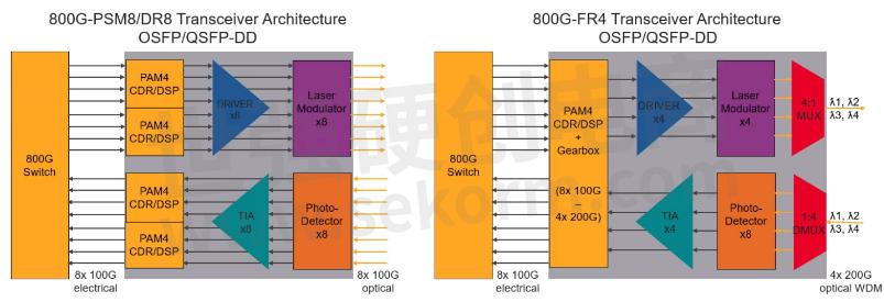
Figure 5. Typical implementations of 800G optical interconnection
The 800G-FR4 4 channel solution brings a new challenge, because the optical module also needs a gearbox to convert 8 channels of 100 Gbps electrical signals into 4 channels of 200 Gbps electrical signals. This then drives 4 optical modulators that can support the corresponding 200 Gbps rate. It is necessary to define a new optical port standard and devices that can handle the higher bandwidth such as DSP, driver, modulator, TIA, etc. At present, this technology is still in the pre-research stage, with modulation mode, baud rate, system bandwidth, link budget, bit error rate, FEC mode, etc. all being explored and discussed.
TECHNICAL CHALLENGES OF 800G ETHERNET
The speed of the previous 400G electrical lanes is doubled to 112 Gbps for the first generation of 800G Ethernet and goes to 4 times (224 Gbps) in the second generation. Interface chips, DSP chips, packaging, connectors etc. all will need performance improvements or new designs to work at the higher speeds. There are already some corresponding standards in the industry that define 112 Gbps electrical ports, such as the OIF CEI-112G family of implementation agreements and the IEEE 802.3ck standard. Both standards bodies define electrical link requirements for various distances or reaches.
- +1 Like
- Add to Favorites
Recommend
- Keysight Makes UK’s First 100Gbps 6G Sub-THz Connection with National Physical Laboratory and University of Surrey
- Keysight Technologies Acquires Quantum Benchmar, Augmenting Keysight‘s Quantum Portfolio
- Keysight Unveils the First Media Access Control Security Test Solution for High Speed Ethernet
- Keysight First to Gain OmniAir Qualified Test Equipment Status, Accelerating C-V2X Device Certification
- Keysight First to Gain GCF Approval of Cases for Validating 5G New Radio mmWave Devices in Standalone Mode
- Keysight Massively Parallel Board Test System Selected by LACROIX in Automotive Printed Circuit Board Manufacturing
- Keysight, TIM and JMA Wireless Join Forces to Showcase O-RAN Technology at Mobile World Congress 2021
- Keysight, Xilinx and Cisco Showcase Solutions that Support Smooth Migration from 4G LTE Networks to 5G Open RAN
This document is provided by Sekorm Platform for VIP exclusive service. The copyright is owned by Sekorm. Without authorization, any medias, websites or individual are not allowed to reprint. When authorizing the reprint, the link of www.sekorm.com must be indicated.
Integrated Circuits


Discrete Components


Connectors & Structural Components


Assembly UnitModules & Accessories


Power Supplies & Power Modules


Electronic Materials


Instrumentation & Test Kit


Electrical Tools & Materials


Mechatronics


Processing & Customization


