The Main Application of RF Circulator

As introduced before, RF circulators are used in a variety of RF circuit design applications. Usually, they tend to be used at microwave frequencies, so they are often called microwave circulators. Here, we will introduce two common applications of circulators.
Duplexer: One of the most common applications for RF circulators is in radar systems or radio communication systems where the transmitter and receiver share an antenna.

RF Circulators Used as Diplexers
For example, the transmitter output is connected to port 1, the antenna to port 2, and the receiver to port 3. Therefore, the transmitter power will cycle to the antenna, not the receiver, and the signal received by the antenna will cycle to the receiver. In this way, the receiver is isolated from the transmitter, but the antenna has power from the transmitter and passes the received signal to the receiver without any mechanical switching.
RF Isolators: RF circulators can be used as RF isolators. This is useful for protecting amplifiers that must operate at high VSWR levels. If connected directly to the antenna under these conditions, the power amplifier may be damaged by exposure to high voltage or current levels.
The transmitters often operate over very wide bandwidths, in these cases it is not possible to maintain a good impedance match across the full bandwidth and it could be seen the destructive damage of VSWR. To overcome this problem, a circulator can be used to protect the PA from reflected power.
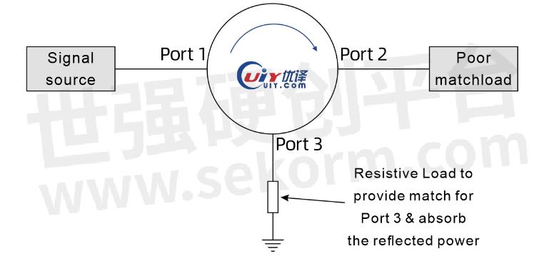
To do this, the transmitter is connected to port 1, the antenna is connected to port 2, and port 3 is usually connected to a 50Ω load – this is required. Because the isolation level depends on a good impedance match presented on the different ports. If there is a mismatch or an open circuit, the isolation performance will be compromised.

RF Circulators Used as RF Isolators
The transmitted power is passed from port 1 to port 2 and transferred to the antenna. Any reflected power will return along the feeder and pass from port 2 to port 3 where it can be absorbed in the load. In this way, the RF power amplifier will be able to operate with high inline VSWR, yet be protected by a circulator acting as an RF isolator.
The load on port 3 needs to provide a matched impedance: The isolator needs to have an impedance matching on the port to maintain the isolation level from that port.
For example, an isolator is connected between a signal generator and a device under test (DUT). If all impedances are matched, the signal can pass freely to the DUT. If the DUT is mismatched or if the DUT is disconnected, a high standing wave ratio (VSWR) will be generated, resulting in a large reflected signal. A circulator absorbs this signal to protect the signal generator, which is always expensive.
- +1 Like
- Add to Favorites
Recommend
This document is provided by Sekorm Platform for VIP exclusive service. The copyright is owned by Sekorm. Without authorization, any medias, websites or individual are not allowed to reprint. When authorizing the reprint, the link of www.sekorm.com must be indicated.


