Lithium-Ion Cell Charging and Discharging During Life Cycle Testing Versus Formation
Lithium-ion cells get charged and discharged, both during life cycle testing and during formation. However, the goals for life cycle testing versus formation are very different. Correspondingly, the charging and discharging, and associated activities, are also very different. Here we will explore the charging and discharging, and associated activities, for life cycle testing and for formation of lithium-ion cells, and how they are different. We will see how this affects the definition of the system solutions for each, making them distinctly different.
Standard Charging and Discharging Protocols for Lithium-Ion Cells
In normal use the standard charging for lithium-ion cells is referred to as CCCV charging. This is illustrated in Figure 1.
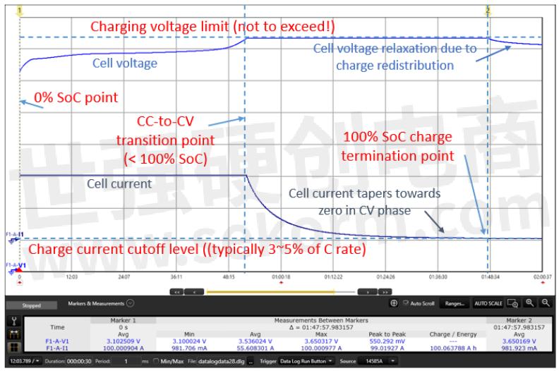
Figure 1: Standard lithium-ion cell CCCV charging
In CCCV charging the cell is first charge by a constant current (CC) at a desired rate, followed by float charging with a constant voltage (CV), equal to the maximum recommended cell voltage. The charging equipment is a constant current power source set to the desired charging current, with a voltage limit set to the maximum recommended cell voltage. A cell's current charging rate is typically specified in terms of its C rate, where 1C would be the constant current rate in amps, equal to the cell's capacity in amp-hours. Thus, 2C would be a charge current set to twice the cell's amp-hour capacity, and so on.
When the cell starts out at a low state of charge (SoC), its voltage is low. As a result, the charger starts out in CC mode during the first phase of the cell's charging. As the cell's SoC increases, so does its voltage. When the cell initially reaches its maximum voltage level, it is usually about 70 to 80% charged, depending on what the C rate is. But because the cell voltage has reached the charger's CV limit setting, the charger automatically transitions to CV mode. During the CV float charging phase the charge current drops exponentially as the remaining charge accumulates in the cell. Full charge, or 100% SoC, is typically defined as when the charge current drops down to about 3 to 5% of the cell's 1C charge rate. When charge current has dropped to this level, the charging is terminated.
Standard discharging is referred to as constant current (CC) discharging. (Of course, for most cases in real life use, the discharging current is typically anything but constant!) CC discharging for a lithium-ion cell is illustrated in Figure 2.
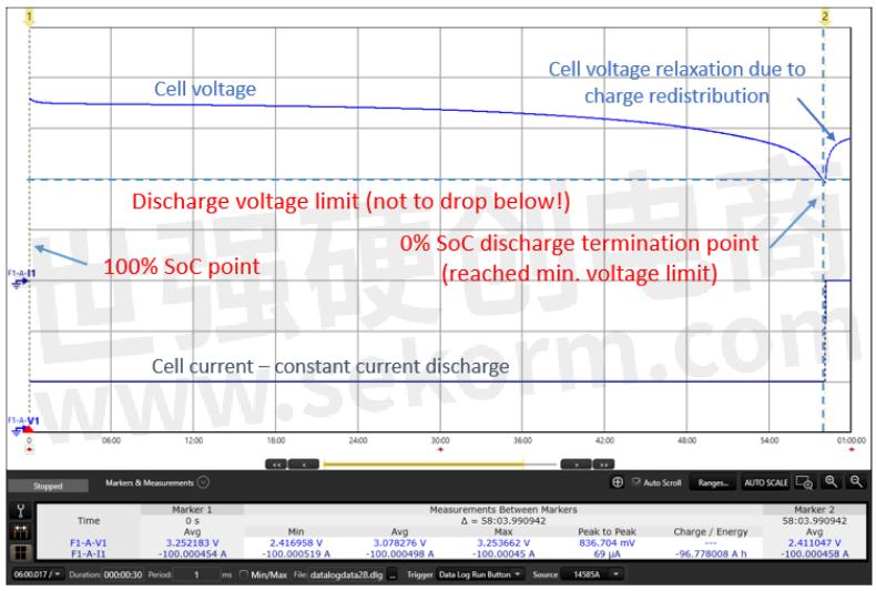
Figure 2: Standard lithium-ion cell CC discharging
Starting at 100% SoC, in CC discharging, current is drawn from the cell at a constant rate until the cell reaches its minimum recommended voltage. This is the point at which the cell is defined to be fully discharge, or at 0% SoC. Any further discharging is terminated. Lithium-ion cells must not be discharged below their minimum recommended voltage as it can cause irreversible damage to them.
Now that the details of the standard charging and discharging protocols have been reviewed, let's look at how charging and discharging is applied in life cycle testing and in formation.
Charging and Discharging During Life Cycle Testing
In lithium-ion cell life cycle testing, a sample group of cells are subjected to many hundreds of charge-discharge cycles over an extended period of typically many months or longer, to predict the cells' charge-discharge cycle end-of-life. The charge and discharge rates may range from 0.5 to several C. Most often standard charging and discharging protocols are used, as described in the previous section. Life cycling is most always performed at elevated temperatures using a temperature chamber, to further accelerate aging.
During the life cycling, the cells are periodically tested for capacity, DC internal resistance (DC-IR), AC internal resistance (AC-IR), and possibly other parameters of specific interest. Very basically, capacity loss over life is the primary concern, where 20% capacity loss is defined the end of (first) life for the cells. The end-of-life number of cycles is predicted by extrapolating from the actual capacity loss measured after exercising the cells hundreds of cycles. This is illustrated in Figure 3. Life cycling may also reveal other things that may lead to premature end-of-life, such as electrode delamination, shorts, and so on. These typically reveal themselves as an abrupt drop in capacity, instead of a gradual loss.

Figure 3: Predicting cells' end-of-cycle-life by extrapolation
System Solutions for Cell Life Cycle Testing
Cycling a large sample of cells at charge and discharge rates from 0.5 to several C requires tens to hundreds of channels of high power, high efficiency regenerative equipment, able to source and sink up to hundreds of amps per channel for today's large format lithium-ion cells. An example of a solution for cell testing and cycling is depicted in Figure 4.

Figure 4: Scienlab SL1007A Cell Level Battery Test System
The Keysight Scienlab SL1007A Battery Test System for cells provides up to 64 independent channels that operate from 0 to 6V. Channels can be configured for 8 output current levels ranging from +/-25A to +/-600A. The SL1007A is very efficient and regenerative, so that it puts the energy back on the AC line when discharging the cells, minimizing electrical consumption and waste heat generation. More importantly, coupled with the SL1091A Scienlab Energy Storage Discover software, it provides a complete, turn-key solution for testing and cycling cells. The Energy Storage Discover software performs and keeps track of cell cycling and performs the required periodic measurements. It supports integrating additional equipment including the climatic chamber and alternative measurement equipment to meet specific customer requirements. Additional features making it a complete solution include:
◆ A flexible and complete database.
◆ Report generation and analytics.
◆ Redundant safety capabilities.
◆ Remote access.
◆ Maintenance and service tracking.
◆ Error handling.
◆ Startup assistance and training.
◆ And much more.
As a basis for an economical cell life-cycling solution, Keysight introduced the BT2205A dual +/-100A, 6V channel module, which is part of the BT2200 Charge-Discharge System. The BT2205A is shown in Figure 5.

Figure 5: The BT2205A dual +/-100A channel module
The BT2200 Charge-Discharge System mainframes can hold up to eight BT2205A modules, providing 16 +/-100A channels. Channels can be paralleled to provide up to +/-800A. Customers can opt to use the BT2200 Charge-Discharge system with the BT2205A module. Multiple BT2200 Charge-Discharge systems can be integrated into a solution for performing cell life cycle testing. This can then be coupled with a cell measurement system, or with a high-performance system such as the Scienlab SL1007A shown in Figure 4, for a hybrid system that uses lower cost equipment for the actual charge-discharge system, for a more economical overall solution.
Cell Charging and Discharging During Formation
Unlike cell life cycle testing, the purpose of formation is to grow a high-quality solid electrolyte interface (SEI) layer on the anodes of all freshly assembled cells in the manufacturing process. Also, in contrast to cell life cycle testing, formation takes place at very low C rates, typically on the order of C/20 to C/10, to produce a high-quality SEI layer that assures long cell life and high performance.
During formation, some of the lithium and electrolyte in the cells are consumed to form the SEI layer. A high-quality SEI layer allows lithium ions to freely pass through, while being electrically non-conductive so that no more electrolyte and lithium can be consumed at the surface of the anode.
If done properly, very little to no additional lithium and electrolyte is consumed in subsequent charge-discharge cycles. However, if the SEI layer is not done properly, additional electrolyte and lithium continues to be consumed, reducing the capacity of the cell over time.
Not only is formation performed at very low C rates, but there are other aspects of formation that make it very different from the standard charge-discharge protocol used for cell life cycle testing. The objective is to form a high-quality SEI layer providing high performance and long life while at the same time minimizing formation time and cost. As I had pointed out in my previous article, the charge-discharge profiles used in formation are a closely guarded company trade secret, considered to provide a competitive advantage over other companies. Also, a protocol that may work well for one cell design may not be well suited for another cell design. Additional unique things about charging and discharging cells during formation that differentiate it from standard cell charge-discharge cycling include:
◆ Some manufacturers may apply a pre-charge step as prelude to the main formation process, to raise the cell potential high enough to prevent corrosion of the copper foil substrate of the negative electrode. They would then let the cell rest for a period before continuing the formation process.
◆ Cells are generally subjected to just a few charge-discharge cycles during formation. Many times, the cells are not fully discharged during formation, as SEI formation primarily takes place at relatively high SoC levels. Manufacturers experiment with a myriad of complex multi-cycle profiles with one cycle being different from the next, to minimize formation time while still assuring a high-performance SEI layer is formed.
◆ The charging and discharging may often be interlaced with different rest periods and fixed-voltage dwell periods, to optimize the SEI formation.
◆ As with cell wetting, formation may be performed at elevated temperatures to help accelerate SEI formation to reduce time. This contrasts with cell life cycling, where higher temperature may be used to accelerate cell wear-out mechanisms.
After cell assembly and filling, an illustrative example of a formation procedure may be as follows:
1. Allow cells to rest 1 hour for wetting.
2. Move cells to a pre-charge station or formation station. Apply a pre-charge at C/30 with 3V limit for 5 minutes.
3. Move cells to a temperature chamber for a 30 degree C soak for 8 hours for full wetting.
4. Move to a formation station:
◆ Apply a CC/CV charge of C/20 with a 4.2V limit. (About 1 day)
◆ Apply a CC discharge of C/20 with a 2.7V cutoff. (About 20 hours)
◆ Apply a C/10 charge to bring the cells to 80% SoC (About 8 hours)
5. Move cells to storage to rest for 1 day.
6. Move cells to a measure station, measure OCV.
7. Move cells to storage to rest for 7 days.
8. Move cells to a measure station, measure OCV and AC-IR.
9. Move cells to a formation station:
◆ Apply a CC/CV charge of C/5 with a 4.2V limit to bring to 100% SoC. (About 2 hours)
◆ Apply a CC discharge of C/5 with a 2.7V limit to bring to 0% SoC, to measure capacity (about 5 hours).
◆ Apply a CC charge of C/5 to bring to 30% SoC for shipping (about 1.5 hours).
10. Move cells to grading, marking, and shipping.
System Solutions for Cell Formation Cycling
Because formation is performed at a much lower C-rate and is done for 100% of the cells in manufacturing, this dictates the need for up to thousands of channels that can charge and discharge cells typically from a couple of amps up to tens of amps. High efficiency, regenerative capabilities, and space savings are all top priorities for the formation electronics used in manufacturing. To address the need, Keysight provides the BT2200 Charge-Discharge System with BT2204B module having 32 +/-6.25A channels, for performing cell formation in manufacturing. A BT2200 Charge-Discharge mainframe holds up to eight BT2204B modules, providing a total of 256 channels per mainframe. Channels can be paralleled for higher current. A BT200 Charge-Discharge System is energy efficient, regenerative, and space efficient. Multiple mainframes are then integrated into production systems to address the needs of the factory formation floor. The BT2200 Charge-Discharge System with BT2204B modules is shown in Figure 6.
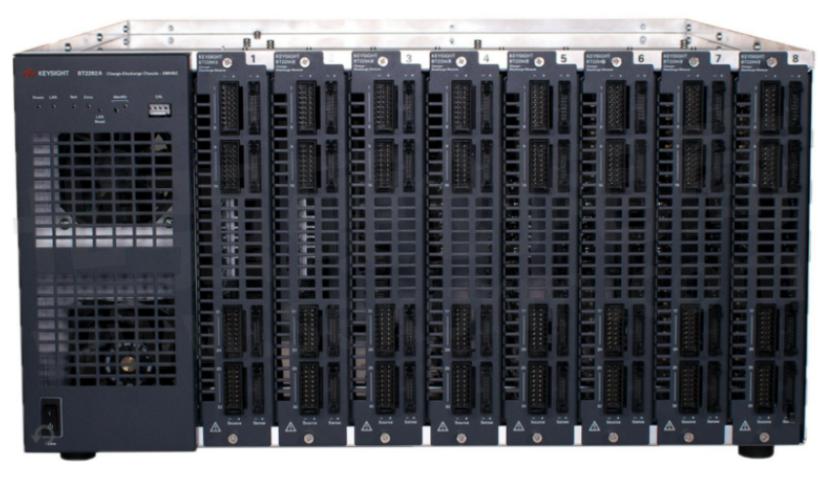
Figure 6: BT2200 Charge-Discharge System with BT2204B modules
Every bit as important for a complete formation solution are the supporting software system and factory floor automation. As can be seen from the example formation process, there are many different types of steps and corresponding stations intermixed with the actual charging and discharging that takes place at the formation station. Lots of cells and associated data and measurement results need to be tracked at each step of the process. The handful of formation charging and discharging cycles performed, while essential, is a smaller part of the integrated formation solution that needs to be considered for the complete formation process. This is in sharp contrast to cell life cycle testing, where the charging and discharging is most of the process.
In addition to providing the BT2200 Charge-Discharge System, Keysight provides tailored software solutions and works with several partners around the world, to help customers implement their factory formation floors for their lithium-ion cell manufacturing facilities.
- +1 Like
- Add to Favorites
Recommend
- Monitor Battery Temperature By Using a Data Acquisition System or Specialized Keysight Scienlab Battery Test System
- Keysight Enhances Test Case Portfolio for e-Mobility Charging with New Scienlab Software
- Keysight Selected by NIO to Verify 5G and Cellular Vehicle to Everything (C-V2X) Connectivity in Electric Vehicles
- Keysight Launches Scienlab Battery Pack Test System with High Voltage Silicon Carbide Technology
- Keysight Solutions Selected by TMYTEK to Verify Performance of Antenna-in-Package Designs in 5G and Satellite Systems
- Chief Marketing Officer of Keysight Shares about Emerging Technology Innovations to Expect in 2023 and Beyond
- Keysight Technologies Acquires Quantum Benchmar, Augmenting Keysight‘s Quantum Portfolio
- Keysight Selected by VTT to Support Open Testing and Integration Facility in Finland
This document is provided by Sekorm Platform for VIP exclusive service. The copyright is owned by Sekorm. Without authorization, any medias, websites or individual are not allowed to reprint. When authorizing the reprint, the link of www.sekorm.com must be indicated.
Integrated Circuits


Discrete Components


Connectors & Structural Components


Assembly UnitModules & Accessories


Power Supplies & Power Modules


Electronic Materials


Instrumentation & Test Kit


Electrical Tools & Materials


Mechatronics


Processing & Customization


