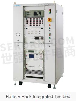
8610 Battery Pack Integrated Testbed for Testing New Energy Vehicle Battery Systems and Subparts | Chroma

CHROMA ATE launches the 8610 Battery Pack Integrated Testbed for testing new energy vehicle battery systems and their subparts, including battery modules, battery management systems, cooling/heating systems, and other related components. Various hardware options are available for integration, such as DC power supply, battery charger/discharge system, digital meter, insulation measurement equipment, and short circuit and overvoltage protection devices.
Key Features:
· Support upper-level automated test software through ASAM XIL and ASAM XIL-MA
· Extensive modular hardware to fulfill test accuracy and repeatability; expandable according to users' needs
· Support CAN, CAN FD, and LIN communication interfaces
· Independent PLC real-time monitoring to ensure safety during battery pack charging and discharging tests
· Built-in AC/DC EVSE charge interfaces, including CAN Bus and PLC communication and related control signals for GB/T, CHAdeMO, and CCS compatibility tests
· Real-time monitoring of timing sequences, including high power relay open/close, initial power output, and CAN signals
· Integrated with Fault Injection Unit to combine fault signals and simulate fault injection
· Support Altair Activate and various Simulink-based real-time models for import to simulate on-road test conditions
· Integrated with Hipot safety analyzer to measure and compare battery insulation and grounding status
Applications:
· Battery pack calibration and verification
· Reliability and durability tests
· Simulation of vehicle driving conditions
· System integration tests
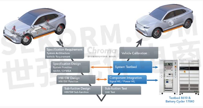
The 8610 system integrated with Chroma’s 17040 Regenerative Battery Pack Test System can simulate the charging and discharging of battery pack using the power system under various driving conditions to increase the test reliability when testing a whole vehicle.
The 8610 Battery Pack Integrated Testbed is designed for research and development of battery modules and packs. The open software architecture offers users powerful dynamics and flexibility while implementing various test items. Besides basic functions like vehicle driving cycle import, CAN signal monitoring, fault injection, insulation measurement, and EVSE charging simulation, this testbed can execute the most complex scenarios of a real vehicle and composite operation conditions with the highest risk of failure (e.g. physical and communication signal errors during cyclic discharge).
The 8610 highly supports the testing requirements on the right side of the vehicle’s standard development, V-shape process, from the integration of battery pack components to the system-level functions. This testbed system can implement various composite and simulated vehicle scenarios in advance before entering a real vehicle test. Users can also discover and correct problems early to reduce development costs and improve test efficiency.
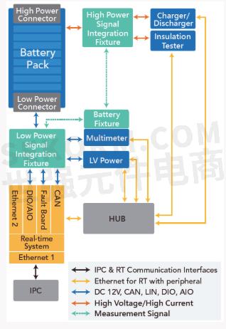
The open software architecture of 8610 can integrate real-time systems, power equipment, measurement modules and simulation models for real-time and highly dynamic testing on battery packs. Compared with other battery test systems that need to obtain the actual on-road charge/discharge records in advance for loading and replay, the 8610 system integrates the driving cycle of vehicle model to directly perform tests on the dynamic battery pack.
On the part of communication, the 8610 testbed supports the common CAN, CAN FD, and LIN interfaces and is capable of loading CAN communication DBC files. For manual testing, it has high flexibility to edit and modify the UI functions so that users can continuously optimize test items and procedures. For automated testing, it supports the upper-level testing software following ASAM XIL and after completion of test sequences, the system's monitoring parameters are recorded for subsequent analysis.
Warning and protection function for system safety
· Warning and protection mechanisms include overcurrent, overvoltage, under voltage, short circuit, power failure detection, system temperature monitoring and others can be expended by users.
· Implement warning, stop, and power cut-off functions through communication data which typically by CAN Bus from battery pack under test.
· Independent PLC real-time system which is capable of integrating monitoring and sensing signals existed already in user’s lab ascertaining the safety of battery pack charging and discharging tests
Highly flexible testing software with intuitive user interface
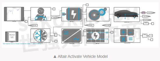
The software structure of 8610 testbed is based on real-time systems, which integrates diverse equipment to establish a control and test program development environment. While supporting the CAN, CAN FD, and LIN communication protocols, the 8610 is capable of setting the battery cycler behavior to interact with battery pack under test synchronously and customizing different testing functions defined by users. Testing engineers can also edit new test sequences based on existing source provided by Chroma and modify the UI to add additional functions. We adopt the Altair Activate vehicle model (depicted below) for vehicle dynamics simulation, for example, importing international standard driving cycles like NEDC, WLTP…etc. to implement dynamic battery pack discharge and regeneration tests.
Main features of user interface and control software
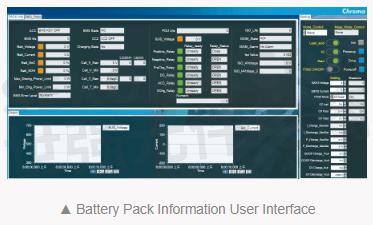
· The monitoring UI can digitally show all testing parameters and update the values in real time through plotting. Related information includes the battery charge/discharge status, voltage, current, SOC, temperature, protection alarm, and insulation level, etc.
· The parameter-control UI can change values or status in real time digitally through dragging or switching. Controlling parameters include battery charge/discharge start and stop, charge/discharge voltage, current and power settings, insulation measurement start, fault injection signal selection, and test condition selection, etc.
· Plot parameter curve while executing testing procedure, and generate report with graphic data after the test is finished. Related parameters include the battery charge/discharge status, voltage, current, SOC, temperature, protection alarm, and insulation level, etc.
· Support the adoption of Altair Activate vehicle model and various Simulink model-based real-time models.
· Sample data synchronously on assorted equipment and adjust sampling frequency by different testing requirements.
· Support manual execution and automatic sequence testing requirements.


Compound Vehicle Scenarios
Test functions for loading vehicle driving cycles such as charging/discharging, signal measurement and control, fault injection, insulation measurement, and simulated EVSE charging are included. Users can arrange and combine all of these test functions with high flexibility to achieve a variety of compound vehicle scenarios, for more comprehensive testing of battery packs. The example below illustrates charging and discharging after loading the real on-road profiles as well as simulation of charging changes right after a fault injection.

Diverse Test Items
Single Test Functions
(1) CC and CV charge/discharge tests
(2) Vehicle driving cycle discharge
(3) Arbitrary charge/discharge pattern reproduction
(4) Voltage measurement and voltage difference detection
(5) Current measurement and current difference detection
(6) High power ON/OFF control logic and timing (relay self-test mechanism confirmation)
(7) High voltage interlocking mechanism
(8) Battery protection function timing check
(9) Insulation resistance measurement
(10) AC/DC withstand voltage tests
(11) Dynamic leakage current
(12) GB/T, CHAdeMO, CCS AC/DC charging and interoperability tests
Compound Test Functions
(1) Checking insulation & withstand voltage status after fault injection while discharging with the imported vehicle driving cycle
(2) Checking insulation & withstand voltage status after fault injection during arbitrary charge/discharge pattern reproduction
(3) Impact of fault injection on SOC calculation and protection functions
(4) Checking insulation & withstand voltage status after fault injection when performing AC and DC charge
(5) Charging energy and strategy verification with different SOC, cell & total voltage and fault signals
(6) Fully charged calibration mechanism test
- 【Datasheet】BATTERY PACK POWER HIL TESTBED MODEL 8610
- 【Datasheet】REGENERATIVE BATTERY PACK TEST SYSTEM MODEL 17040
- 【Datasheet】REGENERATIVE BATTERY PACKTEST SYSTEM MODEL 17040
- 【Datasheet】MODEL 8610 BATTERY PACK POWER HIL TESTBED
- 【Datasheet】MODEL 17040 REGENERATIVE BATTERY PACKTEST SYSTEM
- 【Datasheet】REGENERATIVE BATTERY PACKTEST SYSTEM MODEL 17040
- 【Datasheet】MODEL 17040 REGENERATIVE BATTERY PACK TEST SYSTEM
- 【Datasheet】MODEL 8610 BATTERY PACK INTEGRATED TESTBED
- 【Datasheet】MODEL 1210 E-PROPULSION TEST SYSTEM
- +1 Like
- Add to Favorites
Recommend
- Chroma Launches Next-Generation High-Performance Power IC Test Platform Chroma 3650-S2 Equipped with up to 768 pins, 200Mbps data rate
- Chroma Regenerative Test Solutions Accelerate Net-Zero Transition
- Chroma ATE Showcases Advanced Test Technology to Propel the AI Revolution at SEMICON Taiwan 2023
- Sekorm Became an Official Authorized Distributor of Chroma
- Chroma ATE Inc. Featured in Forbes Asia‘s Best Under A Billion 2023, Showcasing Consistent Top- and Bottom-Line Growth
- Chroma Test Setup for Complete Gamma Measurement on Video Signal Generators
- Chroma 62000d Programmable Bidirectional Dc Power Supplies Have Both Power Source and Load Characteristics
- Chroma ATE in Top 40 Best Taiwan Global Brands
This document is provided by Sekorm Platform for VIP exclusive service. The copyright is owned by Sekorm. Without authorization, any medias, websites or individual are not allowed to reprint. When authorizing the reprint, the link of www.sekorm.com must be indicated.
Integrated Circuits


Discrete Components


Connectors & Structural Components


Assembly UnitModules & Accessories


Power Supplies & Power Modules


Electronic Materials


Instrumentation & Test Kit


Electrical Tools & Materials


Mechatronics


Processing & Customization


