How ATP Protects Your Data and SSDs with HW/FW Power-Loss Protection

Solid state drives (SSDs) are particularly vulnerable to unstable power conditions and unexpected power interruptions. Unlike HDDs, SSDs do not have mechanical parts, so every component is electronic. The internal data management of an SSD involves many operations happening in the background, and every power loss or failure, no matter how short, can mean undue interruption of those operations, which could affect drive performance.
Data is typically written on the SSD in this order:
1. The Host sends data to the SSD.
2. The SSD Storage Controller acknowledges that data has been received.
3. If the SSD does not have a DRAM cache, the Storage Controller moves the data to the NAND flash memory, which is non-volatile memory, so the data is safely stored even when power is terminated. If the SSD has a DRAM cache, the data is moved there first. This is volatile memory, so if power is terminated, the data is lost.
4. The Storage Controller decides when to "Flush" the data from the DRAM cache to the NAND flash memory.
In a normal power shutdown, all data from the host is successfully transmitted to the NAND flash memory. Even if power is cut off, data remains there.
When power is terminated before data is moved or flushed into the SSD, the data may be corrupted or lost.
Four Levels of Power-Loss Protection
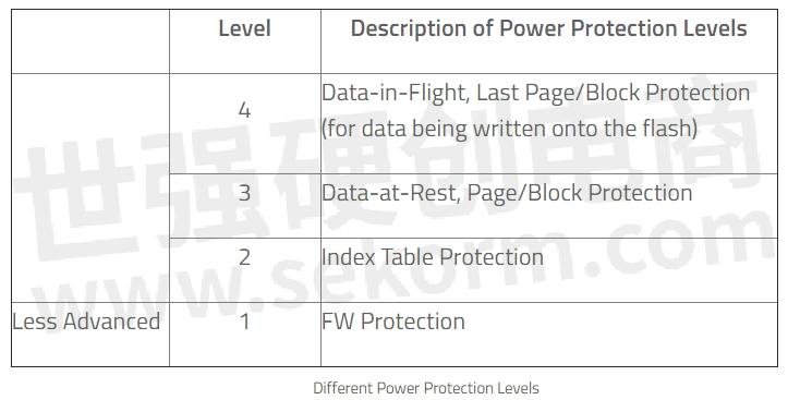
Power-Loss Protection (PLP) mechanisms built into modern solid-state drives (SSDs) can be categorized into four levels:
Damaged Firmware Protection (Level 1). Multiple copies of the firmware (FW) are generated at different times to ensure a backup copy exists in the master firmware that gets corrupted. The master FW is always stored on the strongest flash pages and access is limited to reduce the possibility of reading disturb, and to ensure both FW and data integrity.
Linking Table Damage Protection (Level 2). A NAND flash device creates a linking table to keep track of the physical flash pages with respect to the logical block addresses from the host. The linking table must be maintained and updated constantly so that the host can always access the most updated data via the two mapping addresses recorded on the flash device and the host.
The linking table is cached first and rewritten to the flash from time to time so that the frequent index updating operation does not slow down the ongoing writing performance. When power disruption occurs while some mapping information is still in the flash cache, the mapping index is damaged, along with the data in the flash mapped by the respective linking table. The worst-case scenario is the destruction of the index table, resulting in the loss of all data in the storage device.
Multiple copies of the linking table are backed up for future restore situations when the linking table is distorted or lost during a sudden power loss, thus eliminating the risk of losing all data in a flash device as a result of losing the linking table.
Page/Block Protection (Level 3). Data written on flash chips is divided into segments of millisecond-long operations. If power loss occurs and the writing process is interrupted at one segment point, for example, the 8th millisecond, data error may occur when the host tries to access the part of the data that was lost during the power loss interruption. Level 3 protection ensures completion of the write command prior to power failure, preventing any data loss.

Last Write Page/Block Protection (Level 4). For SSDs with Level 4 protection, data in transit is secured by providing enough power to complete the last program operation before the power loss, guaranteeing that data is safely written onto the flash chip. In the illustration above, the last millisecond-long program operation is completed and data in the 8th segment is safely stored.
The following table summarizes the various levels of power protection to prevent data loss:

ATP Sudden Power-Off Recovery (SPOR): Pure FW Power-Loss Protection
ATP Sudden Power-Off Recovery technology provides firmware-based PLP to minimize the effects of sudden power off.
■ISP Code Backup. As soon as the device is powered On, the temporary in-system programming (ISP) code is generated in a spare block to reduce read access of the main ISP and to reduce the chances of reading disturbed.
■Link Table Mapping Address Backup. After power is on, the FW will trace the link table from the latest mapping address. If the link table is found to be invalid, the FW will search the previous mapping address until the valid one is found. The mapping address is stored on a strong page only to ensure its integrity.
ATP's Superior HW + FW Power-Loss Protection Technology
It is critical to have a power-loss protection (PLP) mechanism, especially in high-performance computing environments where devices are running 24/7, the deployment is extensive, and data, as well as device integrity, could spell the difference between operational failure and success. Protecting stored data is just as crucial as protecting data in transit.
ATP provides state-of-the-art defense against data loss, integrating hardware design and firmware algorithms to deliver the best power-loss protection available today.
ATP harnesses the advantages of tantalum polymer capacitors, featuring low series resistance and minimal sensitivity to temperature and humidity. ATP SSDs with HW+FW PLP technology are assured of high reliability and endurance even in harsh environments. They also enable the HW+FW PLP mechanism to be implemented in small-size SSDs.
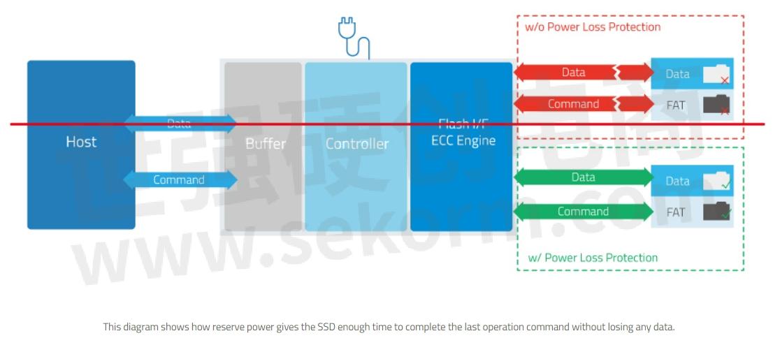
Upon sensing a power loss event, a power loss detection circuit integrated in the SSD immediately activates the power protection mechanism. The SSD then uses up reserve power from capacitors on the drive to complete the last Read, Write or Block Erase operation, while simultaneously stopping the controller from sending data to the flash chip to make sure that no data is lost in transit.

The following diagrams show how ATP's HW+FW PLP prolongs the functionality of the NAND flash in two scenarios, allowing the SSD to complete the last command or data given by the controller.


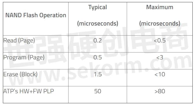
The following table shows the typical and maximum amount of time in microseconds (ms) for ATP's HW+FW PLP to complete various commands during a power loss event.

Microcontroller-Based PLP
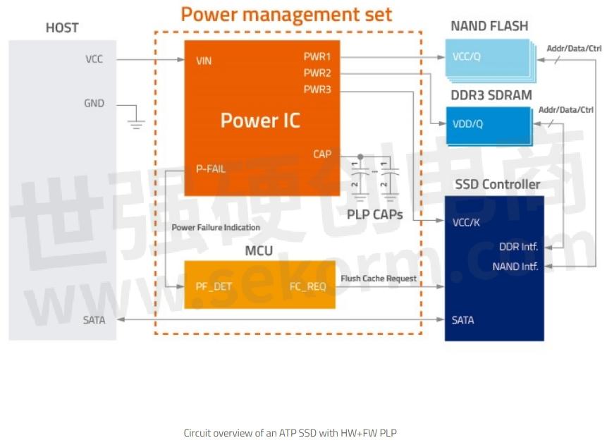
Select SSDs use a microcontroller unit (MCU) that provides unparalleled defense for ATP Serial ATA (SATA) and NVMe SSDs to deliver the best PLP protection in the industry. Integrated into ATP HW+FW PLP, the completely new design of the PLP array utilizes a new power management IC (PMIC) and new firmware‑programmable MCU that allow the PLP array to perform intelligently in various temperatures, power glitches and power states.
MCU-based PLP provides over input voltage protection, power-up inrush current suppression, input power noise de-glitch, fast power on-off control, PLP capacitors over voltage protection, and customization options.

ATP Power Cycling Tester
ATP's own-built power cycling tester validates the design of the PLP mechanism under sudden power-off conditions. At the beginning of each cycle, the power tester writes a segment of data pattern onto the SSD test device. Power is then cut off at the exact configured millisecond while data is being programmed into the NAND flash blocks. By creating a sudden power failure at the "write" command stage, the test proves the effectiveness of the PLP mechanism, showing a "Pass" over thousands of power cycles without any data errors.
During the Power Cycling Test, a window of time for a device without ATP HW+FW PLP is evident during the specific time frame in milliseconds when data loss is most likely to occur with a power glitch. This finding is critical for product development teams to fine-tune the programming of future NAND flash products with their host systems.
The following figures show that a product without the ATP HW+FW PLP will have corrupted data and a "Fail" result due to data miscompare in the post-test check conducted after each power cycle. The product with ATP HW+FW PLP shows a "Pass" result without any data loss.

Conclusion
ATP offers both firmware and hardware solutions aimed at protecting valuable data on an SSD. ATP HW+FW PLP offers advanced power-loss protection to ensure data integrity even during a power failure scenario and to preserve data in mission-critical applications. The PLP mechanism features a standalone design, solid-state capacitors, and long life span.
For SSDs with ATP's MCU-based PLP, the power-loss protection exceeds the performance and reliability offered by other basic backup solutions. Moreover, ATP's Power Cycling Tester, which removes power at the exact millisecond during the programing of the NAND flash product, further validates and improves ATP product lines' overall reliability.
- +1 Like
- Add to Favorites
Recommend
- Apacer Launches AS2280Q4U M.2 Gen4 x4 SSD for PS5 with 7400/7000MB/s Read/Write Speeds
- How Over-Provisioning Can Benefit SSD Performance SSDs
- What Are the Common SSD Myths?
- Apacer‘s Latest Industrial PCIe Gen4 x4 SSD Supports Continuous Read/Write Speeds of 5080/4735MB/s
- The Importance of Crystal Oscillator in SSD, This Article will Let You Understand in Seconds!
- FORESEE XP2300 PCIe SSD: A Flagship Solution Leading the AI PC Memory Revolution
- Apacer‘s SV25T Transformed SSD Is a Quick and Easy Way to Adopt OOB Technology For Organizations Interested In Improving ESG Compliance
- The First FORESEE Large-capacity SSD for Vehicle-mounted Monitoring Systems Supports 24-channel High-definition Recording
This document is provided by Sekorm Platform for VIP exclusive service. The copyright is owned by Sekorm. Without authorization, any medias, websites or individual are not allowed to reprint. When authorizing the reprint, the link of www.sekorm.com must be indicated.


