How to choose Diplexer or Circulator?

A Diplexer(Duplexer) is a three-port passive radio frequency device that is a very common in communications, radar, and other sensing applications. Today UYI will share how to choose duplexer from Circulators in practical applications.
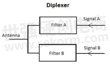
Diplexer(duplexer) consists of two filters of different frequencies connected to an antenna. By using the frequency division function of high-pass, low-pass or band-pass filters, the same antenna or transmission line can use two signal paths, so that the same antenna can receive and transmit signals of two different frequencies.
In the diagram below, signal A enters the duplexer and passes through filter A to the antenna. Signal B passes through filter B to the same antenna. Both signals need to be very different in frequency so that the filter can easily classify them.

Diplexer / Duplexer
According to the multiple application, the diplexer(duplexer) can also be made into a triplexer, a multiplexer, etc.
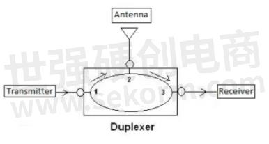
The circulator is also a three-port device, which is a three-port or multi-port device that transmits the incident wave entering its ports into the next port in the direction determined by the static bias magnetic field. Its distinctive feature is that it can transmit high-frequency signal in one direction.

Circulator
So how do choose duplexer from circulators in practical applications?
1、The diplexers(duplexers) are usually chosen to work at different frequencies at the same time; while circulators work at the same frequency at the same time.
2、Cavity duplexer always in high isolation but big size and high insertion loss. It can distinguish uplink and downlink.
The duplexer receives the reflected signal at the receiving end and filters out unwanted signals through the RX channel. For example: 703 to 803MHz – Duplexer / Diplexer
Mechanic size: 155*185*47mm, TX 703 ~ 748; RX 758 ~ 803;
Insertion loss≤1.5dB ripple in band 1.2dB, isolation ≥100dB,VSWR≤1.3dB。

Circulator is comparatively less isolation and smaller in size. It belongs to microwave ferrite components, which control the transmission of microwave signals through ferrite.
Due to the dependence of magnetic field to complete non-reciprocity work, forward insertion loss is very small. The microwave ferrite in the device determines its resonant frequency.
Ferrite circulator TX signal is sent to the antenna interface, because the matching condition of circulator and antenna, it would reflect some of the signal to the RX port.
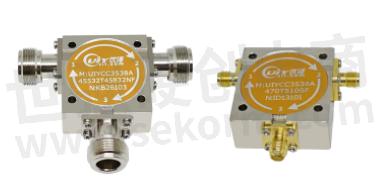
For example: 200 to 1875MHz – Coaxial Circulator
Mechanic size: 35*38*15mm, bandwidth 700~800MHz, isolation≥25dB, Insertion loss≤0.3,VSWR≤1.2.

Therefore, it is necessary to combine specific needs to determine specific products.
- +1 Like
- Add to Favorites
Recommend
This document is provided by Sekorm Platform for VIP exclusive service. The copyright is owned by Sekorm. Without authorization, any medias, websites or individual are not allowed to reprint. When authorizing the reprint, the link of www.sekorm.com must be indicated.


