Testing Active Cables at 112 Gbps Signaling Rate
Efficient sharing of computing and storage resources is critical for data centers and high-performance computing clusters. For this purpose, specialized servers are linked to each other via switches. The first level of connection takes place in the server rack, where servers are interconnected via a top of the rack (TOR) switch using passive and/or active cables. Layer 1 and Layer 2 switches (also called leaf and spine switches) are used to share resources between racks. As they are usually more than 5 meters away from each other, more expensive and power-consuming optical transceiver modules are used for the connections (see Figure 1).
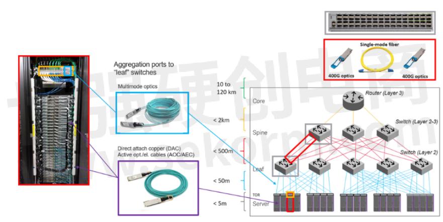
Figure 1: Data center switching architecture
When passive direct-attached copper (DAC) cables are used, the “host” chip of the networking interfaces sitting at each end of the DAC must accommodate for the loss and distortion of the passive copper channel. This sets very stringent requirements on the host chip design and drastically limits the cable reach when operating at 50 Gpbs or 100 Gpbs signaling rates. For this reason, active cables are becoming increasingly popular.
Due to the varying reach objectives, there are several different types of active cables: active copper cables (ACC), active electrical cables (AEC), and active optical cables (AOC).
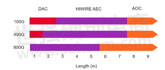
Figure 2: Application space for DAC, AEC and AOC according to the Hiwire consortium
A simple linear amplifier and an analog equalizer are typically used in ACCs, whereas AECs and AOCs include a retimer chip that considerably relaxes requirements on the host chip compared to DAC-cable-based on-clock recovery (CR). The so-called chip-to-module (C2M) interface is identical to the one of optical transceiver modules. Contrary to classical pluggable optical transceivers, there is no need to test the optical client “side”, the link between the two ends of the cable being a cable vendor implementation, only the interface to the host (chip-to-module interface).

Figure 3: OSFP switch capable of supporting AEC (right) or DAC (left) cables.
Both the IBTA (InfiniBand Trade Association) and IEEE (Institute of Electrical and Electronics Engineers) Standards Association provides compliance test procedures to ensure interoperability between active cables and the networking interface of server and switches.

Table 1: Corresponding IEEE and IBTA electrical interfaces. Other combinations of signaling rate, number of lanes, and form factor exist (4&5: The standards are still under development at this point in time).
FEC-AWARE ACTIVE CABLE TESTING
With the advent of PAM4 modulation, a combination of digital equalizers and forward error correction (FEC) must be used to ensure error-free transmission. As a result, the complexity of measurements and test approaches has significantly increased compared to NRZ-based systems. Verifying the performance of transmitters now requires emulating a reference adaptive equalizer that accommodates the combined effects of the transmitter limitations and the transmission channel. Metrics such as vertical eye closure (VEC) and eye height (EH) are measured on a reconstructed eye (see Figure 4).
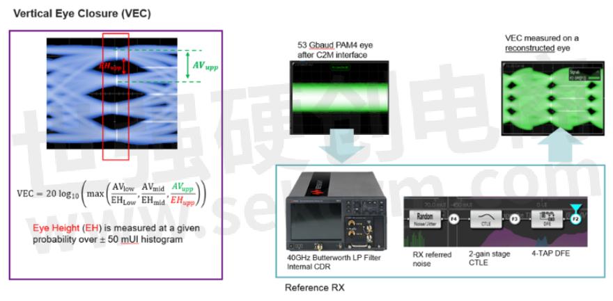
Figure 4: At 53 Gbaud, key metrics such as VEC and EH are measured on a reconstructed signal assuming a reference receiver with equalization capabilities.
When testing the performance of receivers, measuring the raw bit error ratio (BER) is not sufficient anymore at this data speed . Additional performance metrics are needed to qualify system performance:
· Frame loss ratio (FLR): it counts how many Ethernet frames were discarded because errors couldn’t be corrected. It is related to the BER after FEC.
· FEC margin: This describes how far the system operates from the point where the FEC can’t correct bit errors within a frame.
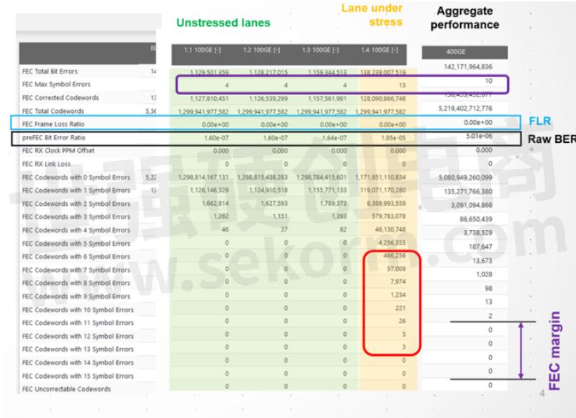
Figure 5: Example of BER, FLR, and FEC margin measurement during stressed input tolerance test
TRANSMITTER TEST
The transmitter test consists in characterizing the output of the module through the mated connector with a module compliance board (MCB). An oscilloscope is the main instrument for transmitter testing. It captures the signal and processes it by emulating the reference receiver described below.
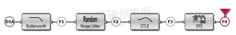
Figure 6: IEEE 802.3ck reference receiver
This reference receiver includes:
· A fourth-order Butterworth filter (40 GHz BW) as a specified receiver noise filter
· Receiver input-referred noise (emulating the intrinsic noise of a realistic receiver)
· A two-gain-stage continuous-time filter (CTLE)
· A four-tap decision-feedback equalizer (DFE)
EH and VEC are measured after the DFE. For more information about the transmitter characterization procedure, please refer to IEEE 802.3ck, Draft 3.2, Annex 120G.3.2.
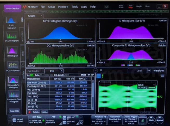
Figure 7: Example of EH and VEC measurements on Keysight Infiniium equivalent-time sampling oscilloscope, using the eye-opening measurement method in annex 120G.5.2.
The values of EH and VEC are the values obtained after the reference receiver equalization. For this, the CTLE DC must be optimized together with the DFE taps. The values of eye height need to comply with the specification for EH (min 15 mV) where it also has a minimum value of VEC. This eye-opening measurement method is referenced from IEEE 802.3ck Draft 3.2, Annex 120G.5.2.
This measurement process can be done using Keysight’s electrical 802.3ck test app (D90103CKC or N1091CKCA).
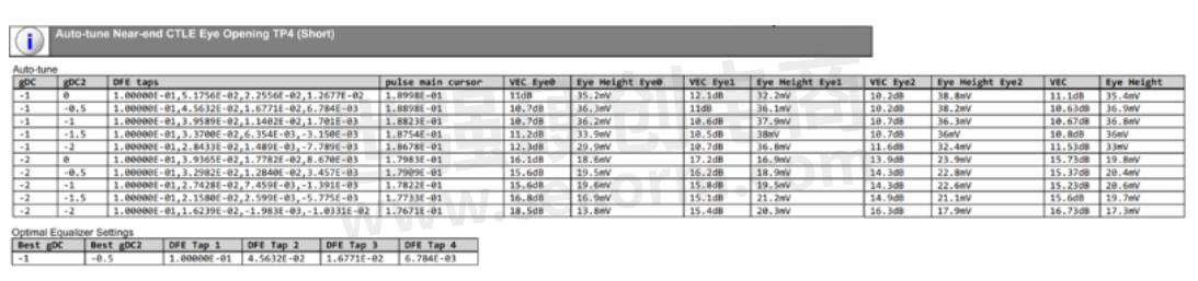
Figure 8: Auto-tune result of AEC, to find the optimal equalizer settings for near-end eye opening
Eye measurement will then use the optimal equalizer setting, to run the near-end EH and near-end VEC.
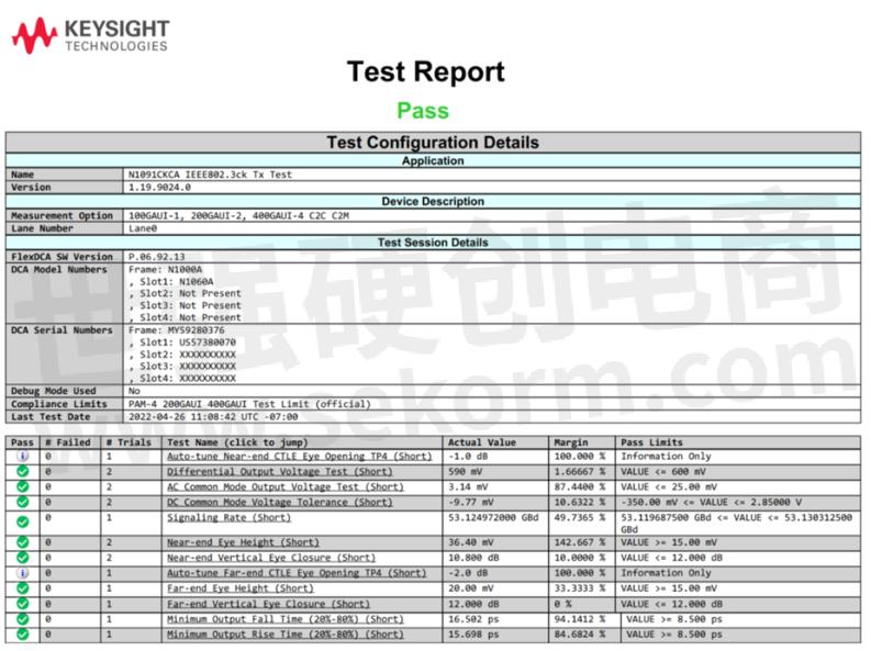
Figure 9: Example of measurement report of chip to module at TP4, with N1091CKCA Electrical IEEE802.3ck test app
RECEIVER TEST
The receiver test consists in testing the module interface with the worst allowable signal coming out of a host.
The receiver test setup consists of Keysight M8040A 64 Gbaud high-performance bit error ratio tester (BERT), a frequency-dependent attenuator or inter-symbol-interference (ISI) board, and a module compliance board (MCB). The pattern generator de-emphasis must be first optimized for the test channel and reference receiver (see section above). After this, its amplitude and jitter profile are tuned to meet the specified VEC and EH prior to performing the stressed input test. For more information about the stressed eye calibration, please refer to IEEE 802.3ck, Draft 3.2, clause 120G.3.4.

Figure 10: Stressed eye calibration results
The Stressed eye calibration results table shows the target EH and VEC to be achieved and the measured values after the CTLE optimization. Besides, the table also indicates the actual amplitude and random jitter (RJ) values to achieve the stressed input test calibration targets.
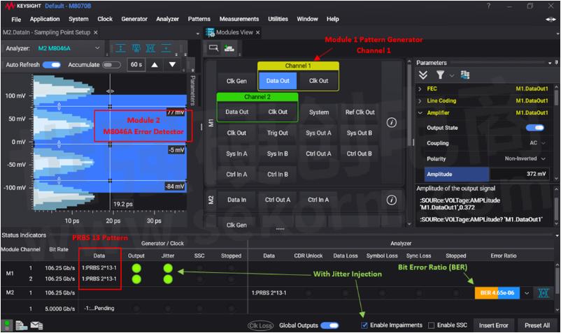
Figure 11: GUI of the BERT firmware for module input test after stressed eye calibration. The DUT passed the test without much margin (BER limit is 1e-5). Without RJ injection, the BER is ~ 1e-7.
KEYSIGHT ACTIVE CABLE TEST SOLUTION
Below is a complete setup for active time-domain (ATD) testing of active cables. It consists of M8040A bit error ratio tester (BERT), M8195A arbitrary waveform generator (AWG), ISI board, DCA sampling scope (N1000A DCA-X mainframe & N1060A precision waveform analyzer), test software (M8070B, N1010A, M8091CKPA & N1091CKCA) & accessories (cables, adapters, etc.)
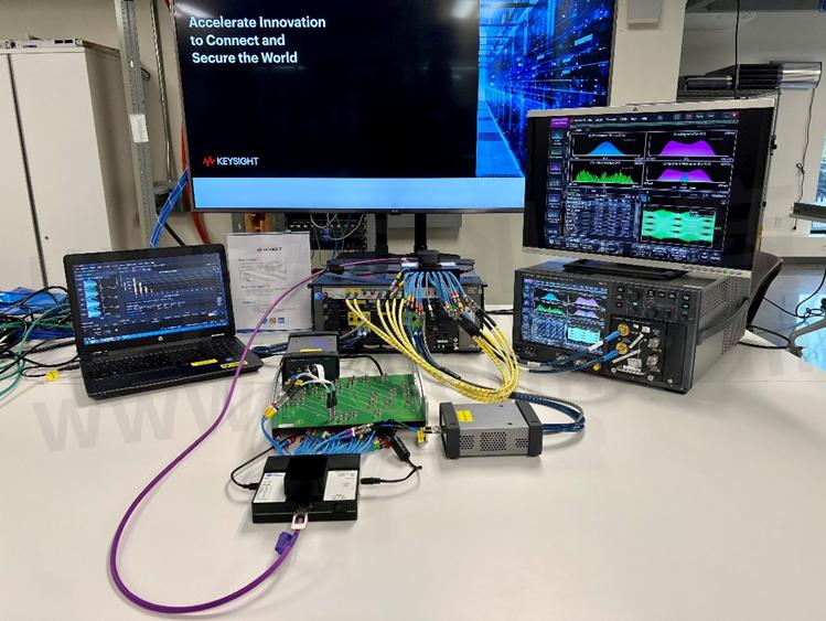
Figure 12: Setup for ATD testing of active cables
The ATD method of testing contemporary high-performance data center interconnects as illustrated in this post, is undergoing review by the IBTA as an effective and more relevant form of a comprehensive test than those methods that preceded this FLR-based ATD technique. A summary of key benefits of this configuration are as follows:
· Evaluation of FLR through up to 8 lanes of striped FEC-encoded signal generation provides highly spec-relevant performance metrics on the performance of the interconnect which are impossible to gain with single-lane test configurations.
· For the first time, an effective means of visualizing error per frame distribution (FEC tail) is provided in this test configuration enabling accurate estimation of the system FEC margin.
· Automated closed-loop signal impairment calibration SW coordinates the time-consuming process of achieving precision scope-based feedback to BERT settings to ensure electrical limits are reached reliably and consistently from run to run or site to site.
- +1 Like
- Add to Favorites
Recommend
- Keysight Delivers Single Vendor Validation Solution for Seamless Support of PCIe® 5.0 and 6.0
- Keysight Technologies Acquires Quantum Benchmar, Augmenting Keysight‘s Quantum Portfolio
- Keysight Participates as Gold Suite Vendor in PCI-SIG® Compliance Workshop to Advance PCI Express® Standards Driving Interoperability
- Keysight First to Gain GCF Approval of Cases for Validating 5G New Radio mmWave Devices in Standalone Mode
- Keysight Delivers First 800G Test Solution for Validating Conformance of 112 Gbps Serial Data Center Interfaces to Latest Industry Standards
- 64 GBaud Bit Error Ratio Tester Secures PCI-SIG Approval for Compliance Test Measuring of PCIe 4.0 Technology
- Keysight‘s O-RAN Test Solutions Enable Xilinx to Accelerate Development of Massive MIMO Radio Reference Design
- Keysight and Transphorm Create Power Supply Reference Design that Lowers Product Costs; Speeds Time to Market
This document is provided by Sekorm Platform for VIP exclusive service. The copyright is owned by Sekorm. Without authorization, any medias, websites or individual are not allowed to reprint. When authorizing the reprint, the link of www.sekorm.com must be indicated.
Integrated Circuits


Discrete Components


Connectors & Structural Components


Assembly UnitModules & Accessories


Power Supplies & Power Modules


Electronic Materials


Instrumentation & Test Kit


Electrical Tools & Materials


Mechatronics


Processing & Customization


