Failure Examples in Dynamic Contact Resistance Testing for Reed Switches

Reed Switches simplify the process of energy transfer through a product or system, but there is much more to a reed switch than what meets the unfamiliar eye. The complexity of the act of "switching" itself and the number of factors that can impact the functionality of a reed switch are key concepts to understand. The health and function of a reed switch is a vital concern that has many threats, which is why Standex Electronics recommends dynamic contact resistance testing.
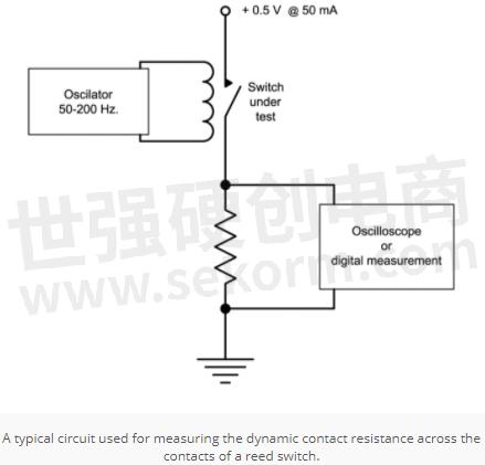
1. What is a Dynamic Contact Resistance Test?
Dynamic contact resistance is a "true" test and a way of measuring the contact resistance of the reed switch blades. This testing ensures that all tools being utilized are not adversely affecting the reed switch. Furthermore, the test eliminates premature failures and improves long term reliability in the equipment and technical systems.
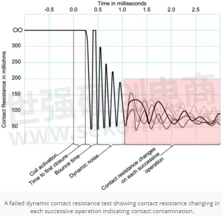
Typical dynamic contact resistance test consists of operating the reed contacts at about 100 times per second. At that rate, users look for a measurement of the contact resistance about 1 millisecond after the contacts close. If the contacts are clean (meaning no contaminants on the contacts) and the reed switch is intact, users usually get a positive result. However, if there is the slightest problem, the contact resistance will not have settled down within one millisecond timeframe. Resulting in a rejected or failed reed switch. A DCR test is the most accurate and efficient way to examine the condition and ability of the reed switch. Additionally, DCR testing helps to determine if anything needs to be corrected during the manufacture of reed switches.
Many things can prove to be a disruption in regards to a reed switch's function. These disruptions listed below can cause a DCR failure:
· Overstressed reed switch usually from assembly
· Small crack on the reed seal
· Broken reed switch
· Plating or sputtering peeling off the contact area
· Air contamination in the glass capsule
· Particles on the reed contacts
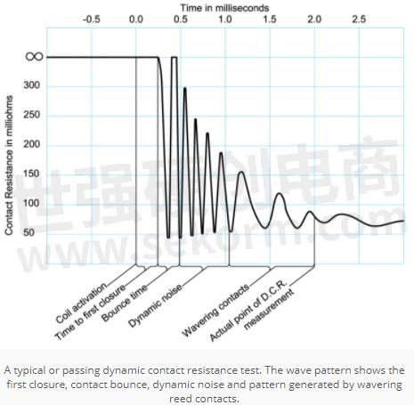
2. What DCR Test Failures Look Like
Below are some examples of electrical patterns showing various DCR failures.
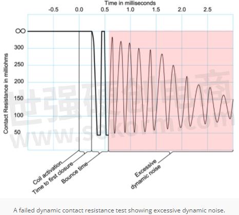
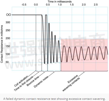
1) DCR Failure "Excessive Contact Bounce" indicating a weak contact closing force sure to shorten the life of the switch

2) DCR Failure "Excessive Dynamic Noise" and "Excessive Contact Wavering" both caused by potential stressed or cracked glass switch seal
3) DCR Failure "Changing Contact Resistance" caused by contact contamination, seal leak, particles, or peeling plating
3. Dynamic Contact Resistance Test Factors
When completing a DCR test, there are a few different factors that will determine the approach of the test that is taken. For example, the test that you run and the results that you get will be based on the below five factors.
· Reed switch size
· The inductance of its coil
· Harmonic motion
· The voltage
· The overdrive level
Larger reed switches have more inertia and the reed blades are stiffer. This causes an increase in the initial reed closure time, the need for magnetically stronger, more inductive coil and the increase of the effects of the critically dampened harmonic motion. Conversely, smaller reed switches have less inertia, are more flexible, and subsequently will behave in the opposite manner of larger reed switches. Reed switch size and the successive inductance of its coil can have a major influence in the dynamic switching characteristics. When the reed contacts come together, they do so with a certain momentum that makes the reeds vibrate. Vibration that is referred to as critically dampening harmonic motion which is an important concept in DCR testing.
When the reeds undergo the critically damped harmonic motion, they are moving microscopically inside the glass capsule. The movement is occurring in the magnetic field generated by the coil and when the metal is in motion in the magnetic field a current will be induced in the metal. This current is a critical part of the measurement of DCR testing. The overdrive of the coil is also a critical parameter in making the DCR measurement. Essentially, it is the voltage (or current) above the actual pull-in (or closure point) where the DCR measurement is made.
4. Conclusion
Reed switches provide us with a unique ability to utilize opening and closing contacts in virtually any environment with a simple magnet, enabling a large space for switching innovation. Dynamic contact resistance testing is a must in order to ensure a fault free operation, maximum efficiency and continued reed switching innovation. For this reason, Standex Electronics DCR tests 100% of its reed-switch based components to ensure customers get the highest quality and reliability.
- +1 Like
- Add to Favorites
Recommend
- Reed Switches Are Quickly Becoming the New Magnetic Sensing Technology of Choice for Low Power Designs
- Latest Littelfuse Ultra-Miniature 7 mm Reed Switches Provide High-Reliability, Longer Life Cycles
- Reed Switches vs. Hall Effect Switches,Two Sensor Solutions for Technical Applications
- Latest Littelfuse Sub-miniature 12.7mm Reed Switches MATE-12B Provide High-Reliability, Longer Life Cycles
- Why and How to Choose Standex Electronics Reed switches
- LS03 Series Standard Liquid Level Sensor for Horizontally Mounting, Feature Magnetic Floats which Activate Reed Switches When the Liquid Level Rises or Falls
- What Are the Advantages of the Hall Switch Over the Reed Switch?
- Standex Electronics Announces the MK33 SMD Reed Switch Series: Optimized to Switch High Power in a Small Footprint
This document is provided by Sekorm Platform for VIP exclusive service. The copyright is owned by Sekorm. Without authorization, any medias, websites or individual are not allowed to reprint. When authorizing the reprint, the link of www.sekorm.com must be indicated.
Integrated Circuits


Discrete Components


Connectors & Structural Components


Assembly UnitModules & Accessories


Power Supplies & Power Modules


Electronic Materials


Instrumentation & Test Kit


Electrical Tools & Materials


Mechatronics


Processing & Customization


